Secondary mirror offset
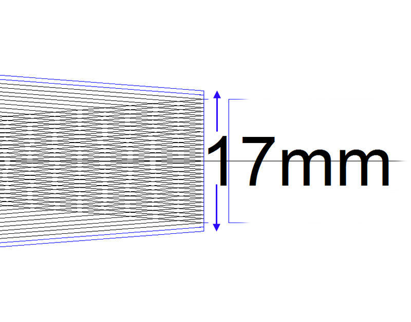
Draw everything to scale. The intention is to make sure that a circle of diameter 17mm on the CCD chip can 'see' the entire primary mirror.First draw the chip at the prime focus of the primary, ie, on the optical axis. (Position A)
Then calculate how far the chip is displaced from the optical axis when the camera is in place in the focuser and draw the chip in position. (Position B)
Now draw lines from both edges of the primary to arrive at regular points across the chip at position A.
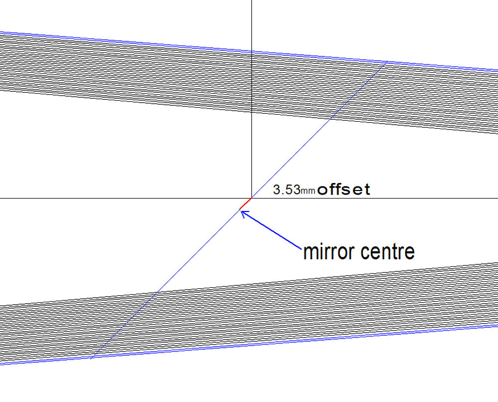
Put the secondary in position at 45° to the axis opposite position B. All the lines must pass through the secondary.
Measure the offset.


Make a paper template the size of the secondary. Cut a hole where the optical axis should be. The template is placed on the mirror with tape and a laser directed to hit the hole. This ensures that the focuser axis and primary axis intersect at the correct place on the secondary.
With the template still in position, the secondary can be rotated and tilted until the laser dot strikes the centre of the primary mirror.
The secondary should now be in perfect alignment.
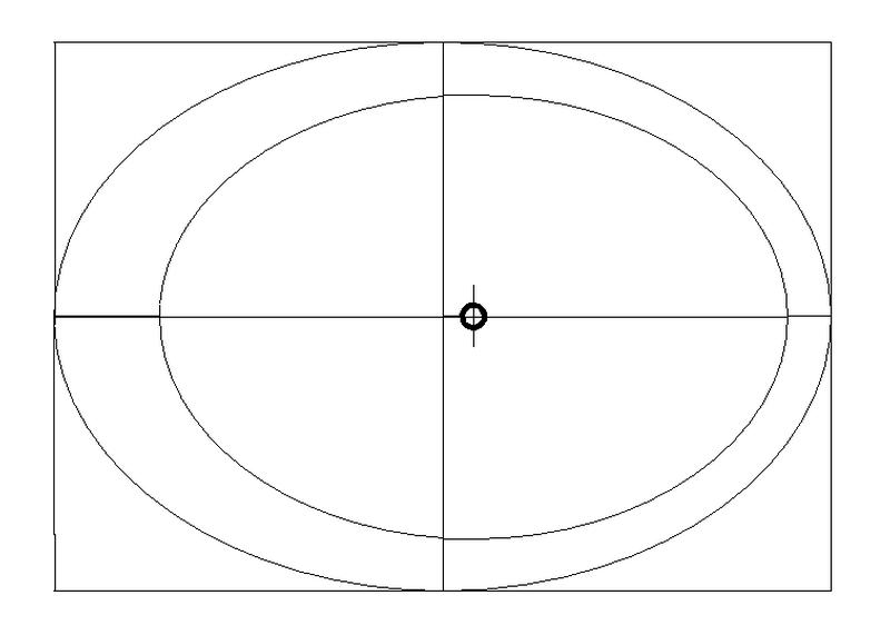
(The smaller ellipse is the outline of the secondary mirror holder. The mirror is glued onto this with three blobs of silicon, see image ).
Alternatively, make a card template and fix threads to intersect at the axis point.
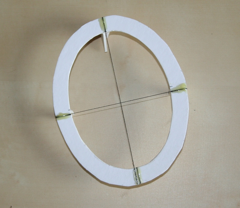
Photo taken looking down the focuser tube.
Everything (except the shadow of the secondary) is concentric.