I ordered a 10" mirror from Carl Zambuto - widely recognised as a superior mirror maker.
The surface accuracy of a Zambuto mirror can be around 1/30th the wavelength of light.
With mirrors of this quality the image should be perfect, only limited by the seeing conditions.
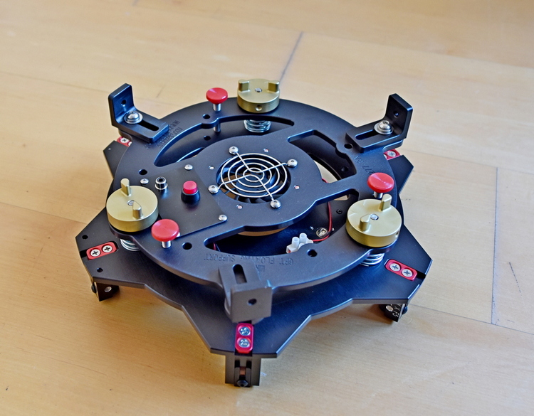
The mirror cell is made by Aurora Precision, optimised for a Zambuto 10".
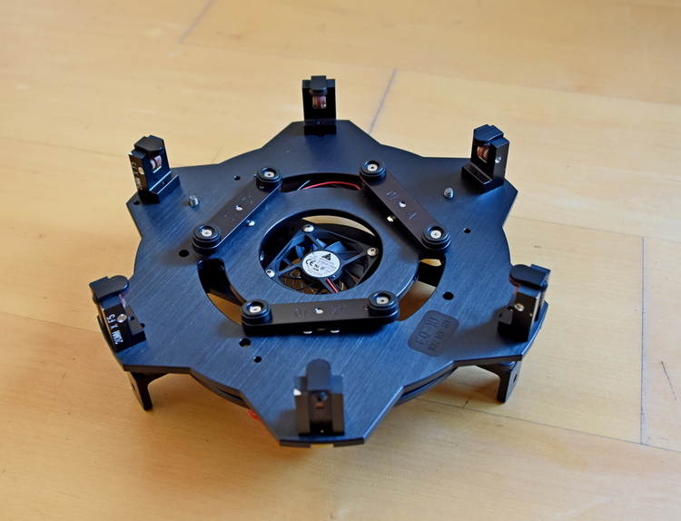
A primary of that quality needs an excellent secondary.
This is 3.1" minor axis, at 1/30 wave from Antares Optics.
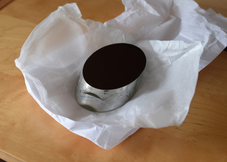
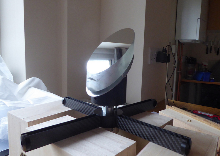
The secondary mirror spider. Carbon fibre vanes.
From TS Optics - the Teleskop Service Brand.
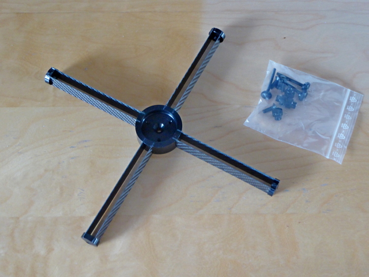
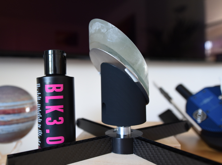
The spider with a novel mirror support.
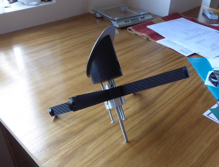
The steel ellipse is held in place with three neodymium magnets and a central bolt.
It will allow very fine alteration of the position of the secondary.
The magnets.
This video shows the method of attachment of the secondary to the support:
link to Youtube Video ---------->>
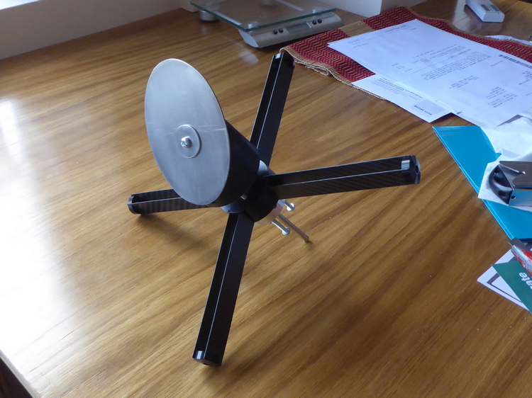
The assembled secondary.
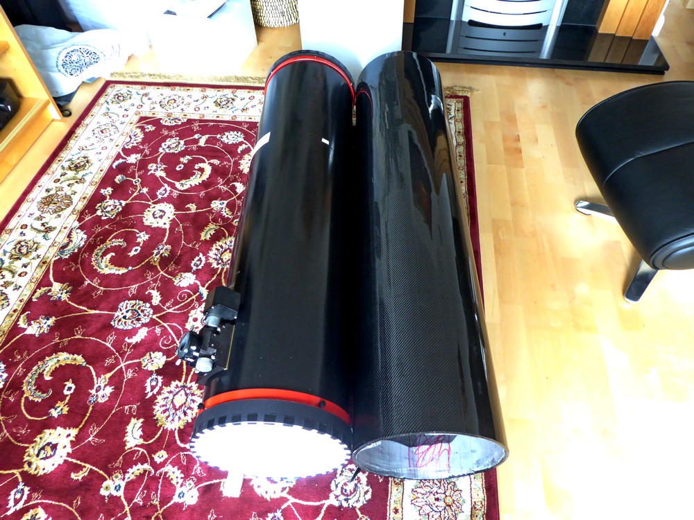
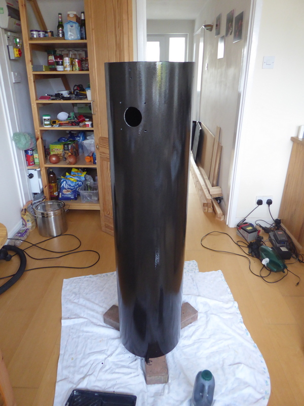
The telescope tube will be from my existing homemade 10".
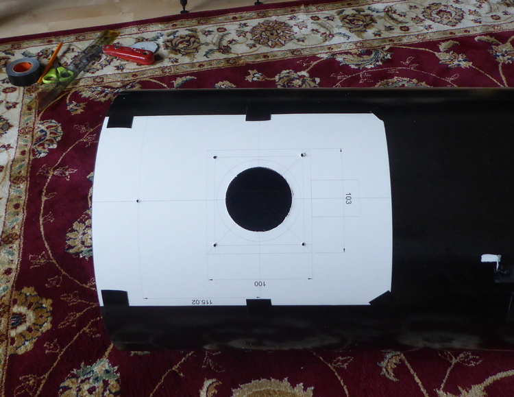
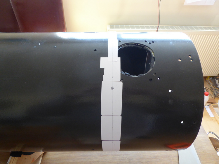
Marking the hole for the focuser with a template.
Secondary mirror fitted.
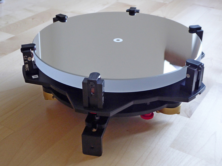
The miror in its cell.
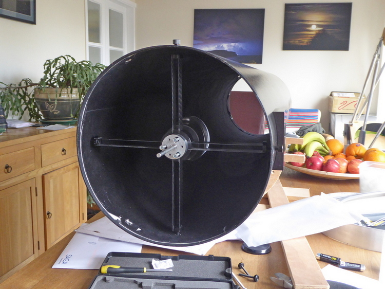
The primary fitted. Note the old focuser hole to the right.
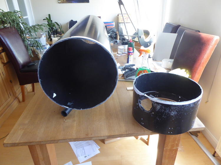
The new scope is f5 - the old one was f6 so the tube will be shorter.
It was neater to turn the tube around and cut a new hole for the focuser.
Surplus will be cut off when positions are finalised.
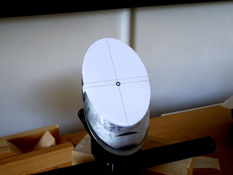
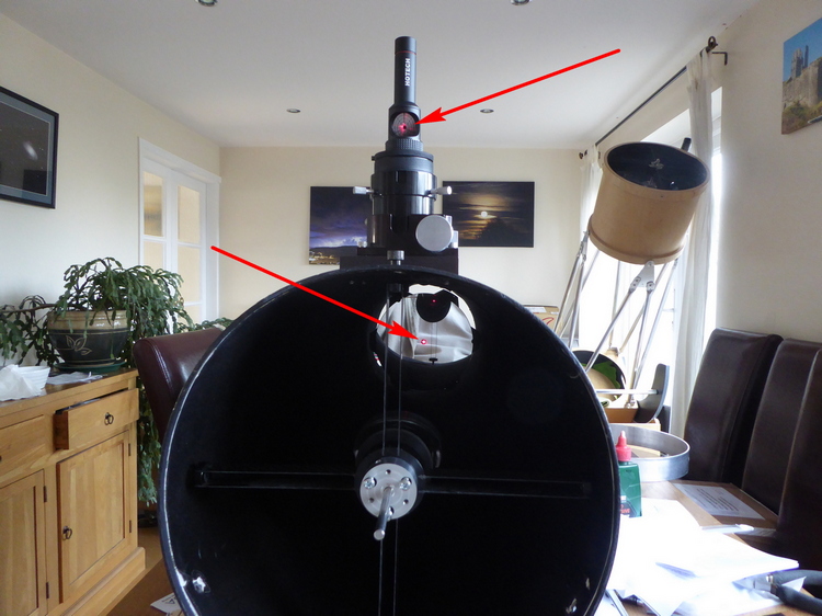
I use a laser collimator to position the secondary accurately.
This template is positioned over the secondary.
The laser beam should hit the small circle.
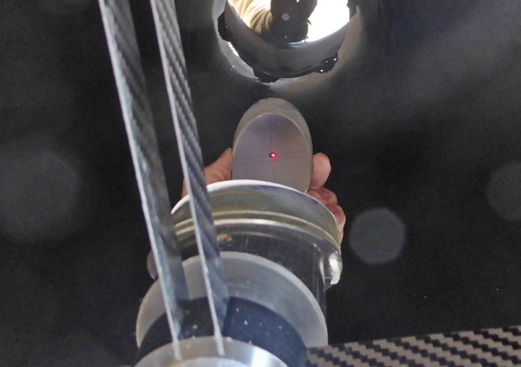
Laser collimator in place
Laser beam on target - viewed by holding small mirror inside the tube.
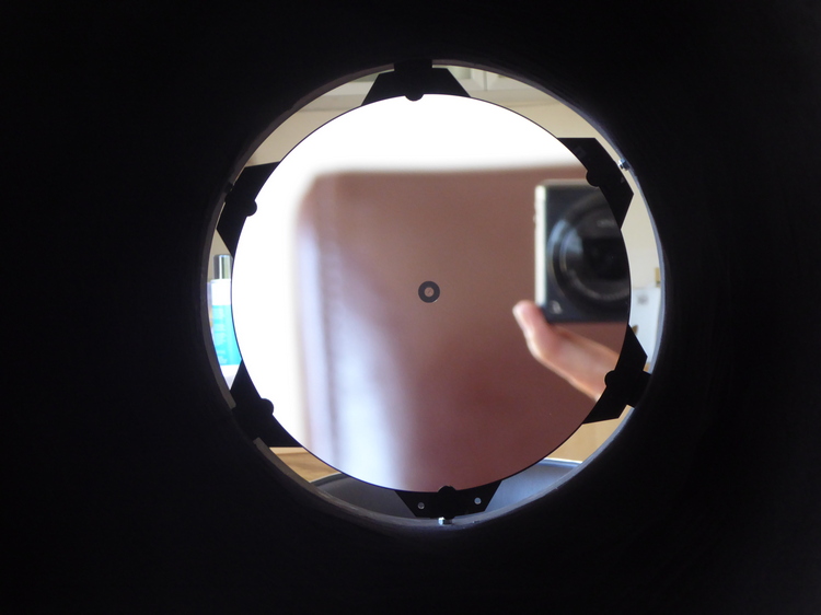
The view down the focuser tube - looks good - nice and concentric.
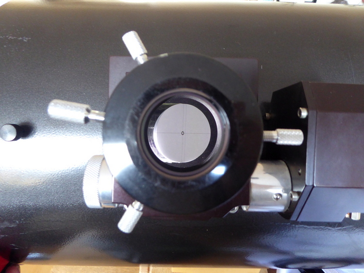
Collimation - the paper template removed and the laser beam reflects down to
the centre of the primary and returns to the laser collimator.
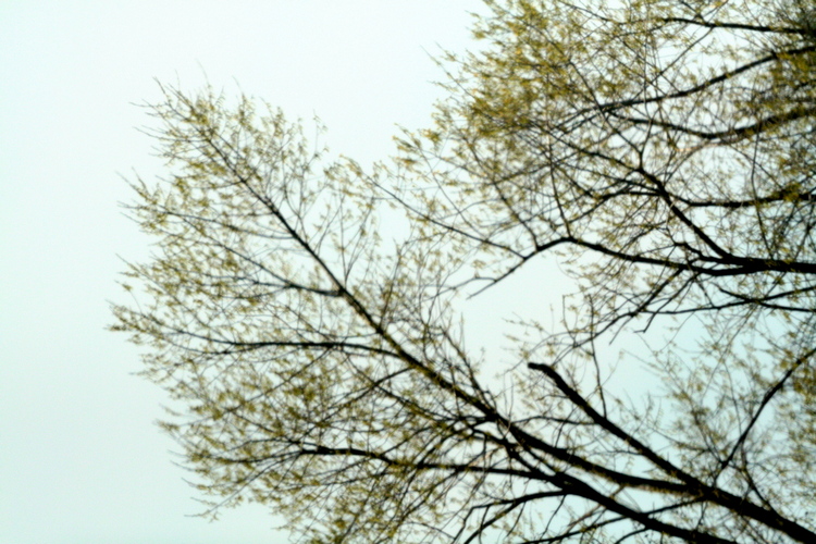
I checked focus using a DSLR and the telescope aimed out of an upstairs window.
Focus was reached with the focuser racked a bit far outwards.
Ideally I want it to be 3mm from its lowest position.
Distant trees. Through double glazing so lousy image...
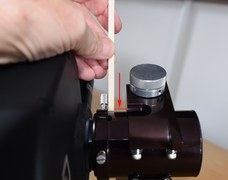
This shows the ideal 3mm gap (arrowed),
This allow the autofocus routine to move either side of focus.
Next step is to check the focus point using the QSI camera.
There will be a difference between it and the DSLR position.
I placed the scope on its end pointing up through the observatory aperture.
Then connected the leads to the camera and took some images.
When stars were roughly in focus I set a 130 second exposure.
As the stars moved across the sky I altered the focus position by 20 steps, every 10 seconds.
The resulting star trails showed the best focus position.
(The numerous small dots are hot pixels - I did not bother turning the ccd cooler on for this test.)
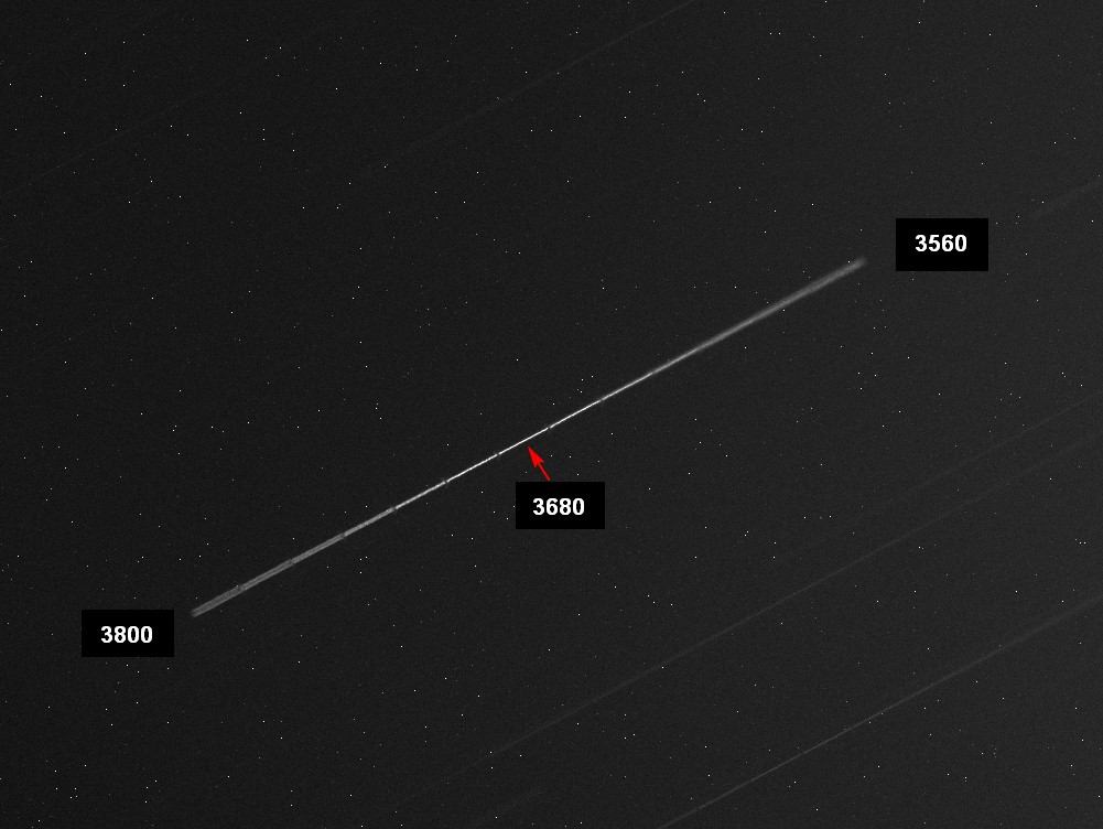
Clearly good focus is at position 3680 on the focuser control.
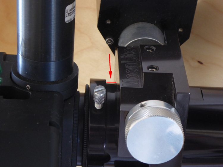
This shows the focus position and the 10.8mm that I need to move the primary mirror back down the tube.
The stick of wood was the width of the required optimum position.
Another clear night so the new focus point checked. Perhaps 2mm from
what I was aiming at but this can be adjusted in the final assembly.
The old tube cut to size and freshened up with a coat of paint.
I was lucky - the old focuser hole did not get in the way!
Aluminium strengthening bands for the ends of the tube - painted red:
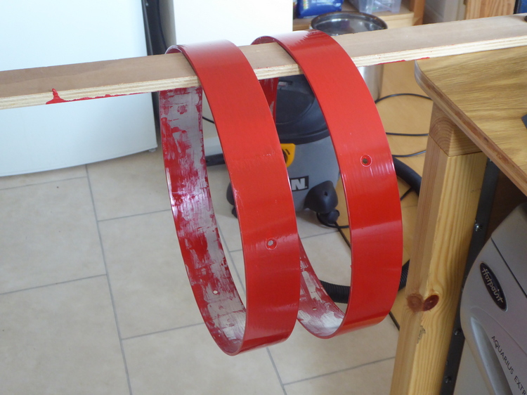
Rings fitted.
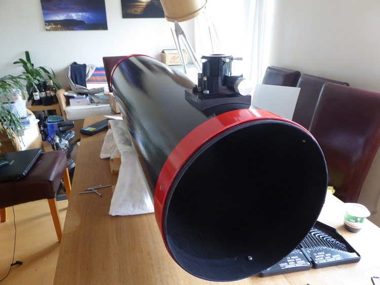
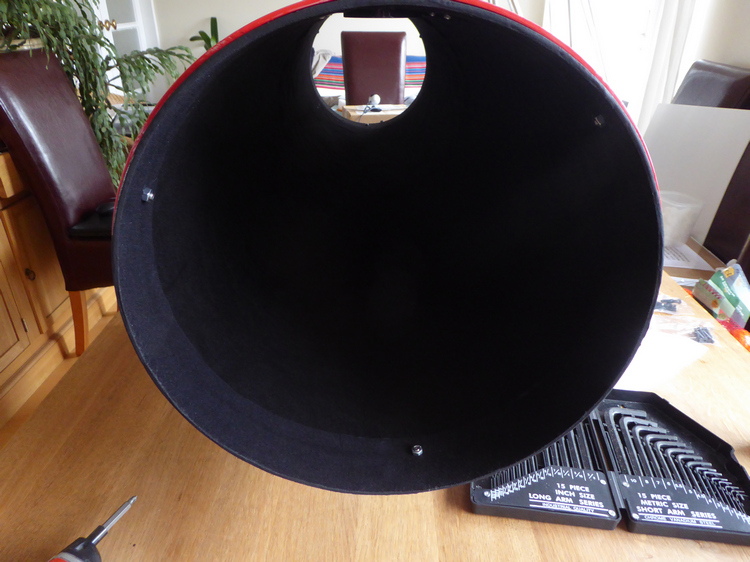
Outer 3 inches of flocking replaced - the old was a bit tatty.
Flocking reflects very little light. Internal reflections will be minimal.
Secondary support painted with Black 3.0 - almost totally non-reflective paint.
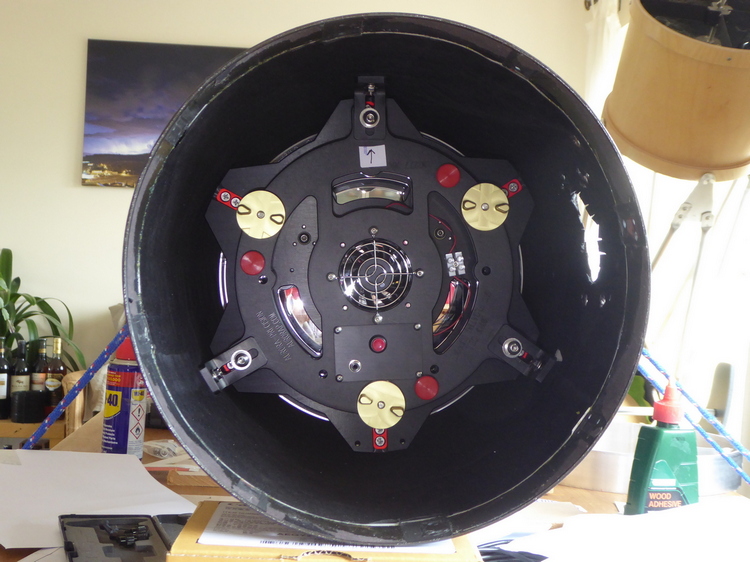
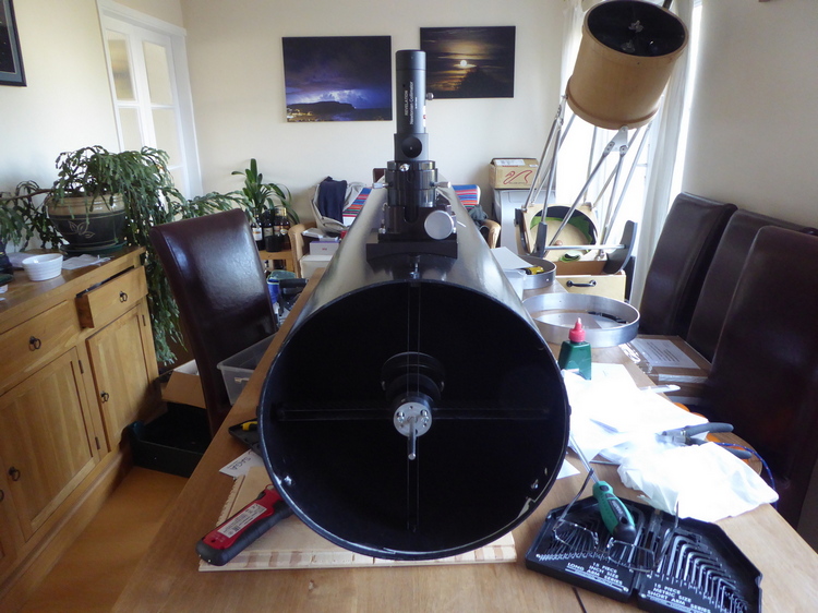
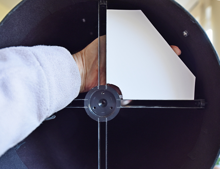
The primary mirror is now in its cell and in situ in the tube.
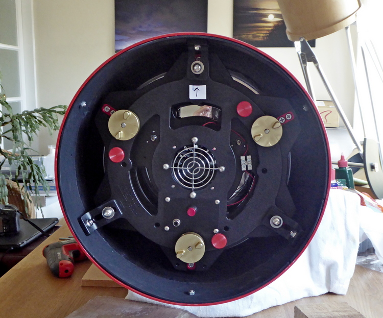
Each fixing point has a series of lines - the trick is to get all 3 points showing the same number of markings.
The tube is not perfectly circular, so this required quite a bit of adjustment.
However, all three are now exactly the same, at 2 units.
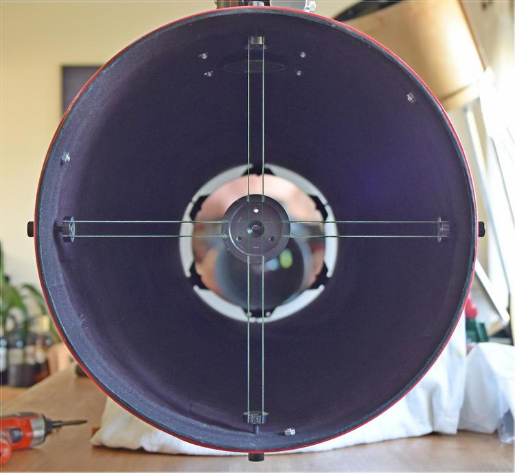
It is important to adjust the spider support so that the vanes
are exactly perpendicular, otherwise diffraction spikes are split.
An accurate 90 template is made from the corner of a foam board.
Checked with a photograph overlaid with lines in a CAD program.
When the vanes are not at 90 degree spacings this effect occurs:
Inserting the secondary and rough collimation. Link to video --------->>
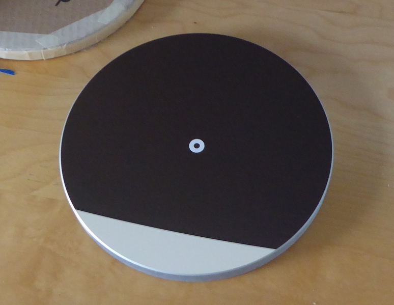
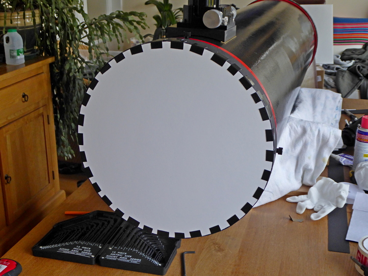
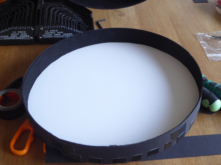
End caps made.
Very light weight. Foam board, adhesive felt cloth, Gorilla tape.
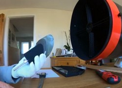
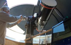
Being in quarantine, getting the new scope onto the mount is a problem. It is a two man job.
In the past I have had a friend help. I made a table/stand to put the telescope on (if I can lift it!).
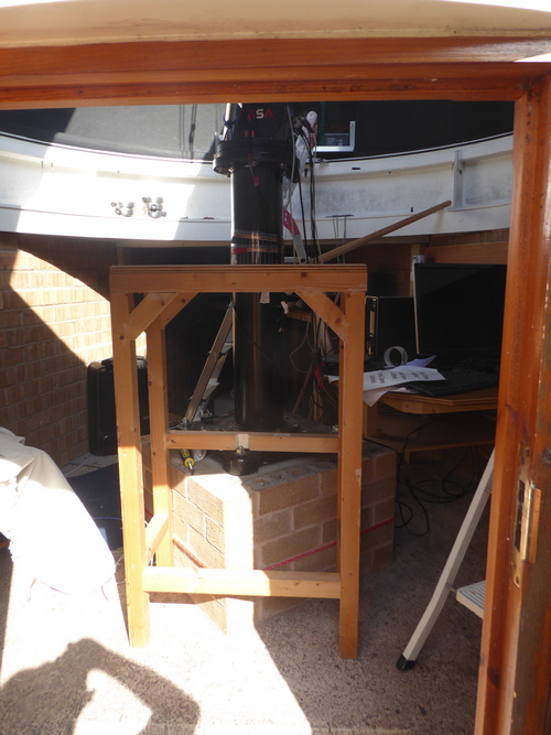
The table was then tied to the pier with ropes for added security.
Also the mount was held in a suitable orientation with ropes to the dome top.
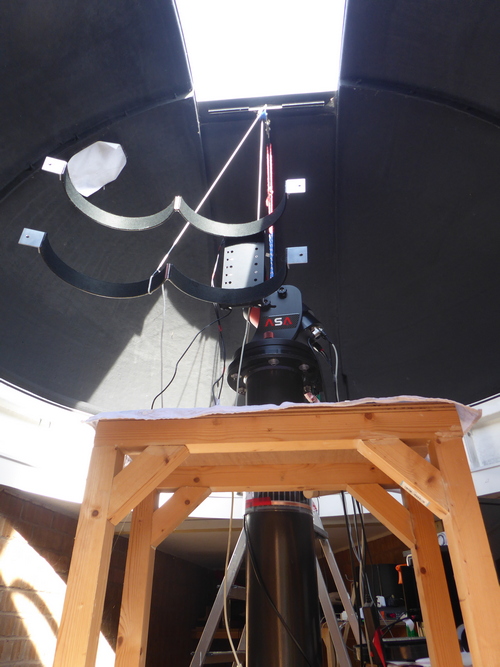
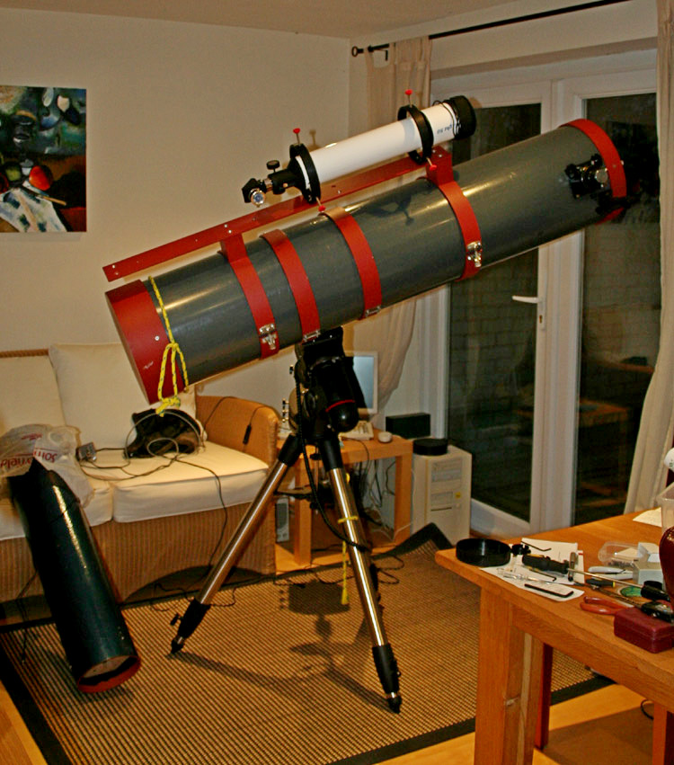
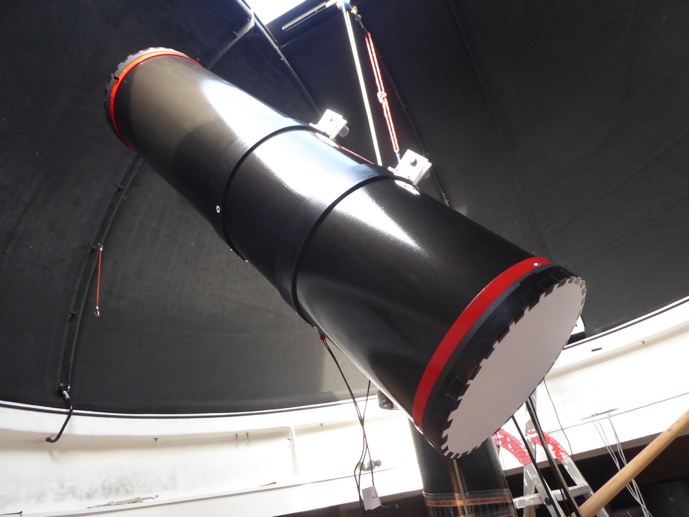
Success. Scope placed upright and tube rings closed. Now to add counterweights...
Roughly balanced and table removed.
Slight adjustments made to collimation. Previously it was collimated in a horizontal position.
In use the scope will never be horizontal.
Next job will be to put the CCD camera on and get 'First Light'.
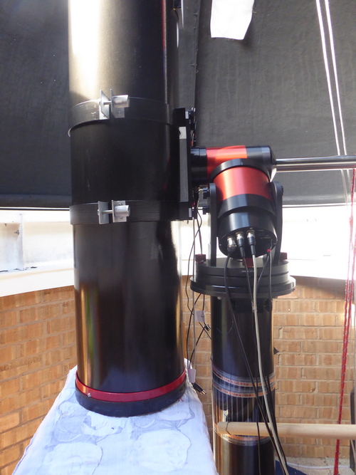
QSI camera now in place.
The mount is a direct drive ASA DDM60, so needs very accurate balancing.
There are no gears - magnetic fields alone control the position and movement of the mount.
If it is unbalanced then the electronics is constantly doing extra work to hold it in place.
Setting up the scope - link to video ----->
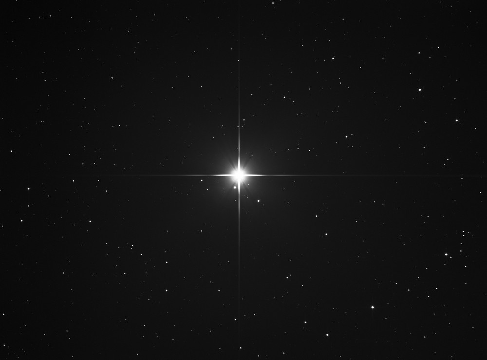
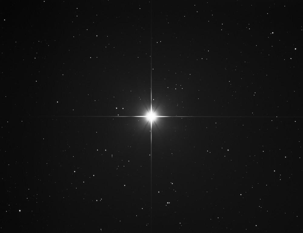
First light April 24th 2020
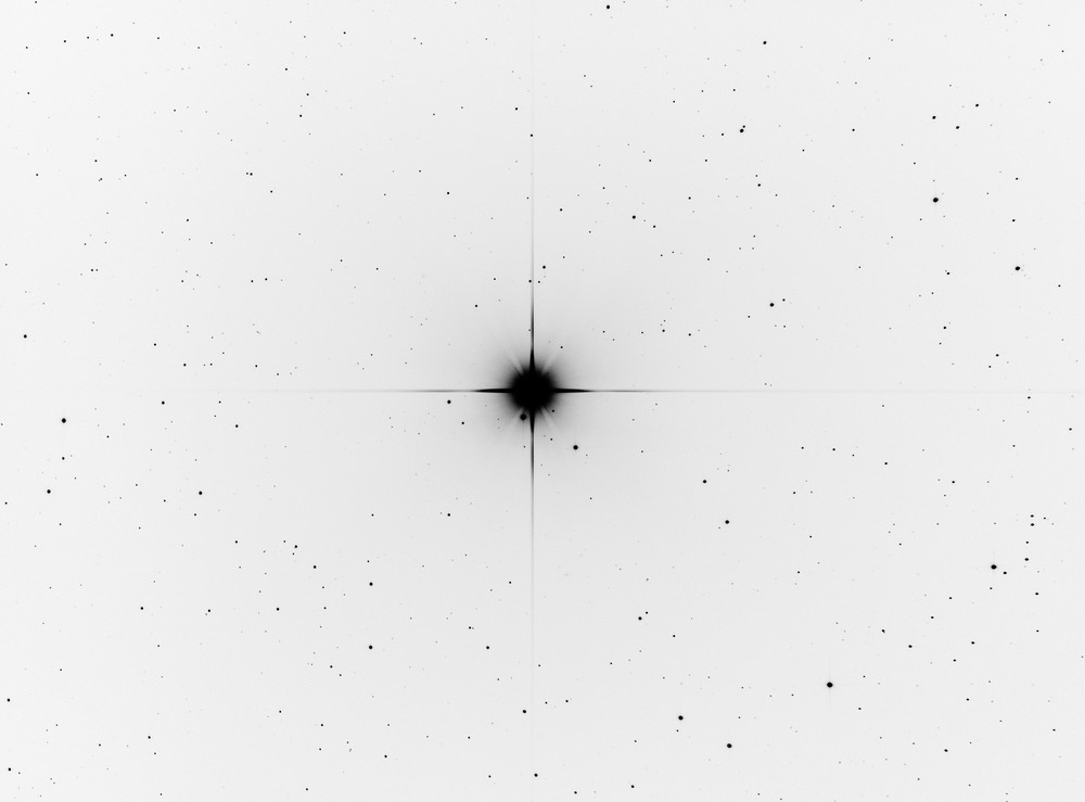
This is 8 x 60 seconds on Castor
Negative image
First impressions are good. Stars are round. Diffraction around Castor is symmetrical with no weird flaring.
Stars at the right of the frame less round - this could be due to camera tilt.
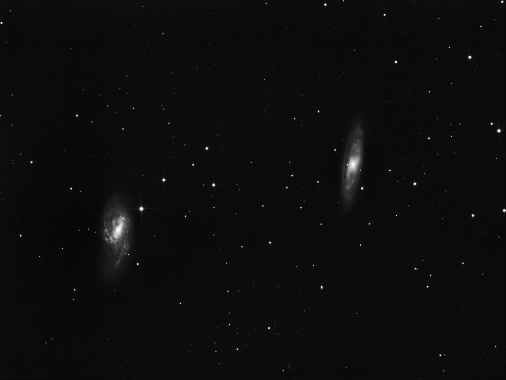
4 x 600 seconds of M65 and M66
Some tweeks.
The images last night were not aligned with North exactly vertical.
The secondary vanes will make diffraction spikes on bright stars.
My intention is to get those spikes aligned NSEW.

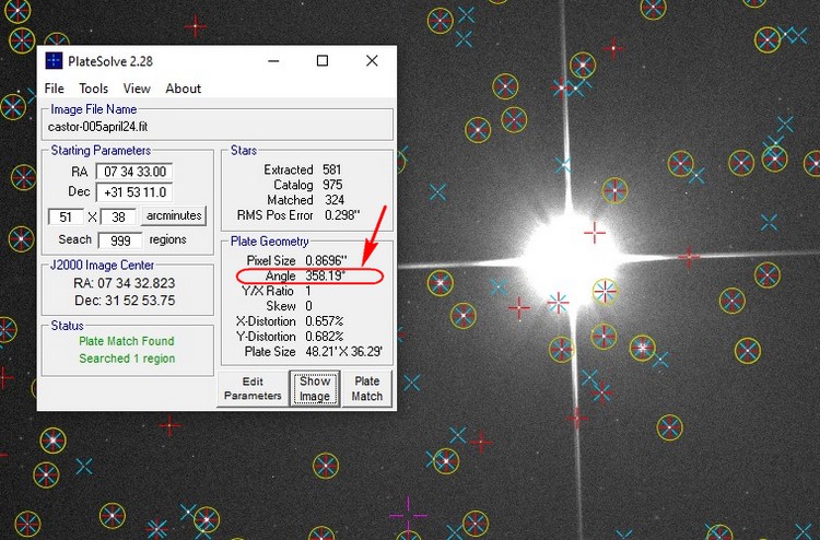
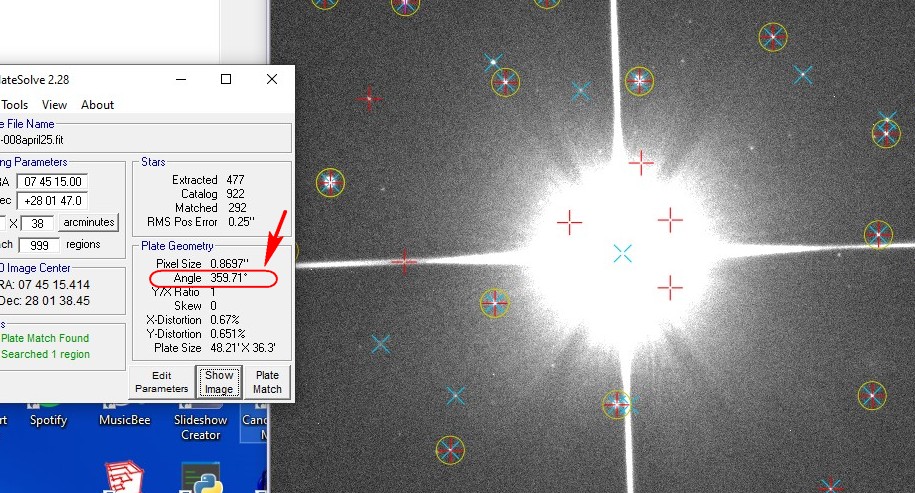
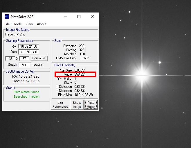
Platesolving an image shows a rotation angle of 358.19
The platesolve also gives useful data such as plate size, pixel size etc.
There are two things that cause this.
1. The telescope tube is rotated within the tube rings.
2. The camera is rotated a bit on the focuser.
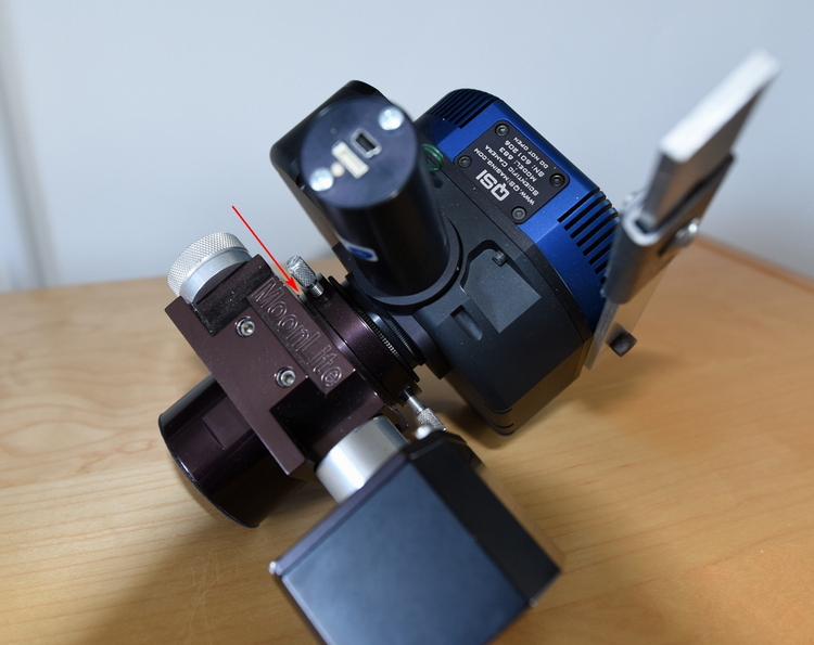
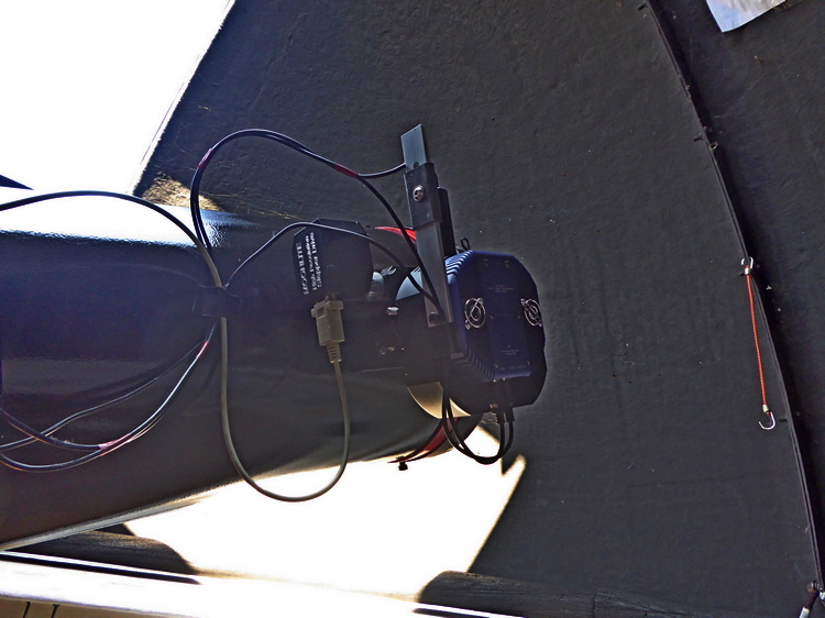
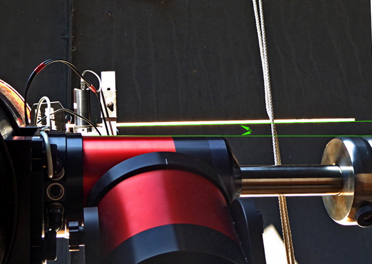
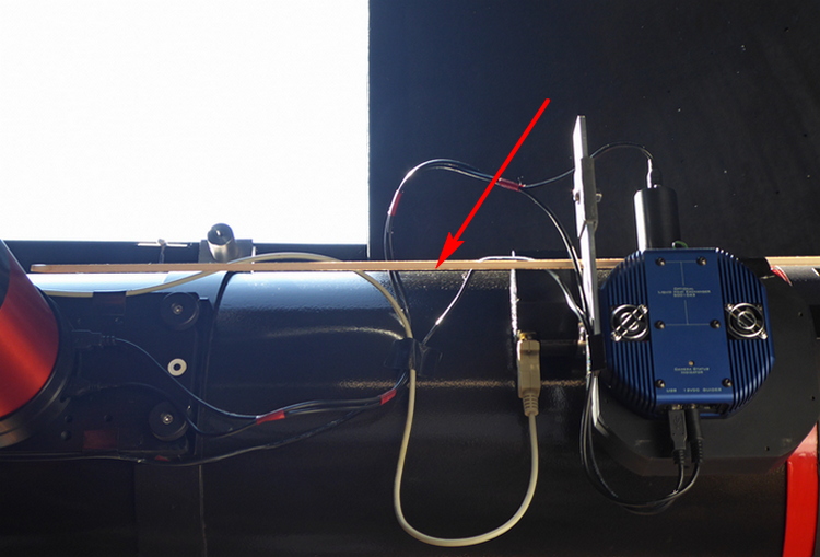
To check the first case I attached a lightweight balsa wood rod to a flat face on the camera.
The rod should be parallel to the declination axis on the mount.
Clearly quite an error!
The telescope tube is heavy and when the tube rings are loosened the scope tends to slip in large jumps.
It is difficult to rotate it fractions of a degree.
Then when the tube rings are tightend they can shift the orientation of the telescope.
Also, the scope tends to slip down in the rings so the declination axis is no longer balanced.
Several attempts are needed before a satisfactory alignment is reached:
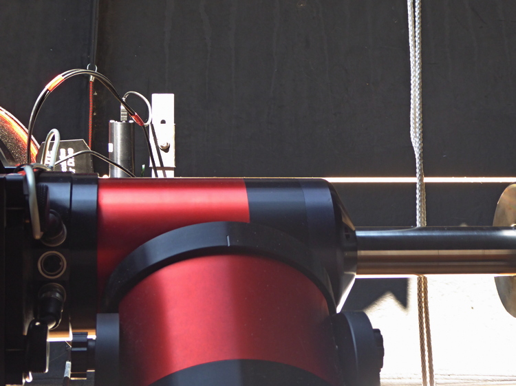
Checking the second case - the rod is attached to a face of the camera that should be parallel to the scope tube.
This looked very good - no adjustments made. The camera and focuser were accurately aligned when on the 8" scope,
and I have not separated them since.
The next images will reveal how far off I still am.
If I can get less than 0.3 degrees error I will be happy.
I got to the <0.3 degrees, but forgot one thing - rotating the scope in the tube rings rotates the North direction
but does NOT change the diffraction spikes angle in relation to the frame.
That angle depends solely on the orientation of the camera in the focuser tube.
Angle error was 0.29 degrees.
The secret is to first rotate the camera to get diffraction spikes aligned, and THEN rotate the scope in the tube rings.
This was Pollux, 10 x 60 seconds.
(I rotated the image to align spikes after processing.)
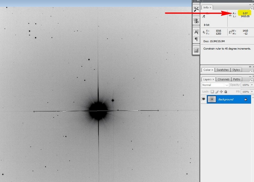
May 4th
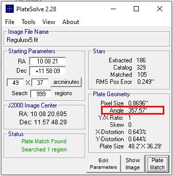
Camera rotated anticlockwise some more. 5x69 seconds on Regulus. Diffraction spikes now 0.5 degrees off.
A bit more to do.
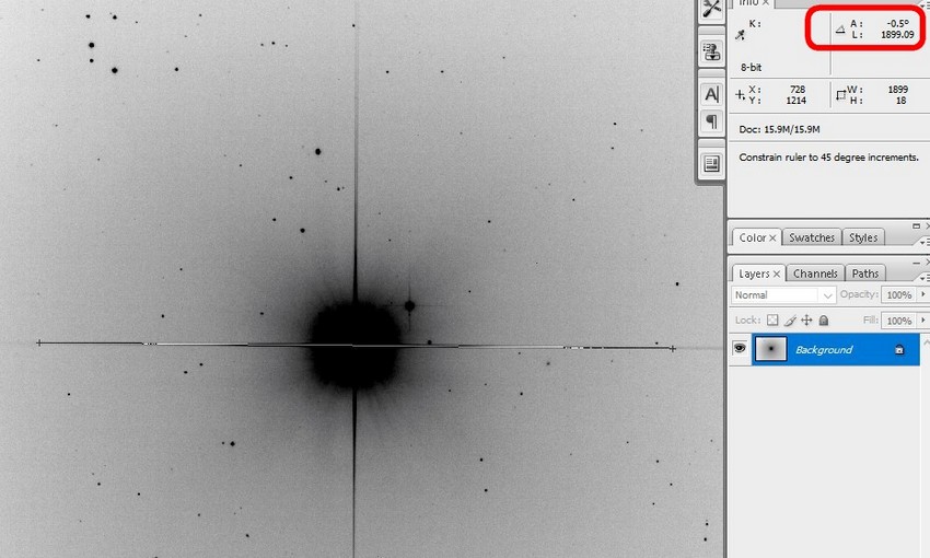
May 5th
Corrected too much the other way, now -0.5 degrees.
It is very difficult to loosen the three screws holding the camera in the focuser and rotate by such tiny angles.
But, it has to be done!
May 6th
Camera alignment now spot on!
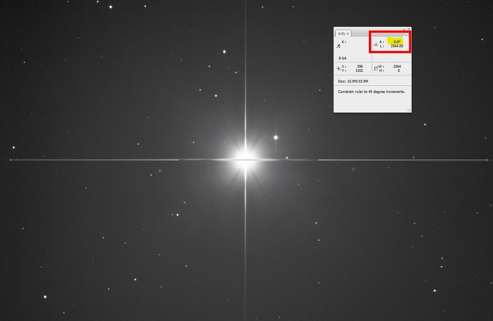
The camera is aligned, and diffraction spikes are vertical and horizontal, but the celestial North is not yet aligned.
The scope tube has to be rotated in the tube rings, by 1.18 degrees.
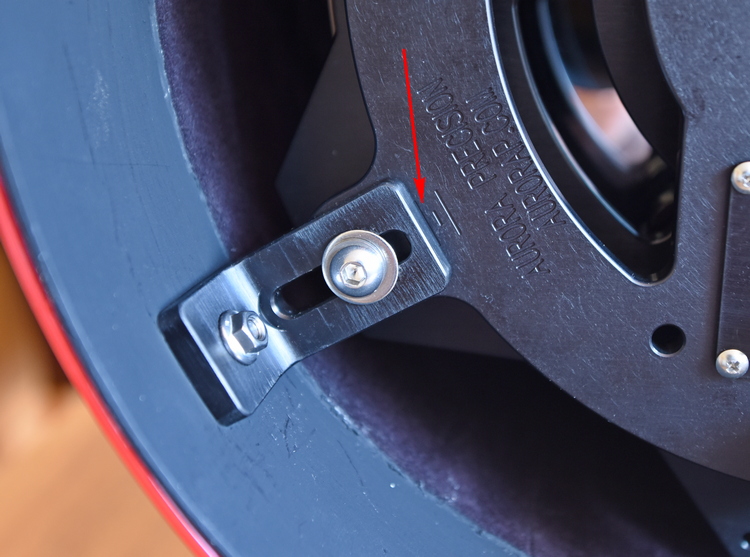
I have made a reticle device to allow an accurate rotation:
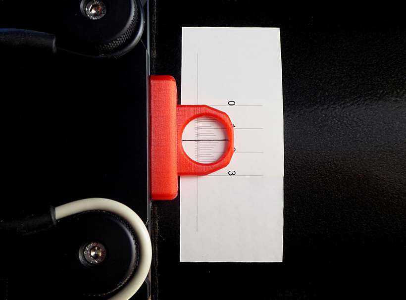
1.18 degrees will correspond to 3.19mm on the reticle.
7th May
I struggled with working out whether the rotation should be clockwise or anticlockwise.
Newtonians do strange things with camera inversions...
Standing at the rear of the scope I rotated the tube anticlockwise by 3.2mm on the scale.
Wrong way! The error has doubled.
Almost exactly doubled - at least shows my maths is correct.
11th May
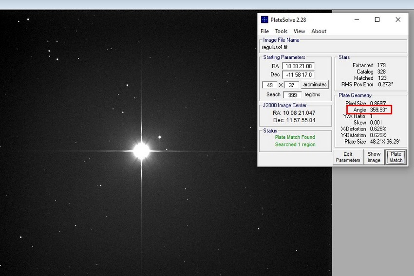
Success. The platesolve shows an error of only 0.07 degrees.
12th May
Is it worth trying to get alignment better than 0.07 degrees?
I measured several images of Regulus at 60 seconds and a few of M61 at 600 seconds.
Platesolved using Pinpoint and Platesolve2.
Pinpoint appears to measure the angle going anticlockwise, Platesolve2 clockwise.
| Platesolve | Pinpoint | |
| Error | Error | |
| Regulus 60 seconds | 359.95 | 0.039 |
| 359.94 | 0.031 | |
| 359.94 | 0.035 | |
| 359.94 | 0.032 | |
| 359.94 | 0.035 | |
| 359.94 | 0.033 | |
| 359.94 | 0.039 | |
| M61 600 seconds | ||
| 359.86 | 0.152 | |
| 359.85 | 0.129 | |
Clearly there is quite a variation in the measured angle - the variations
are greater than 0.07 degrees so no advantage gained in trying to improve.
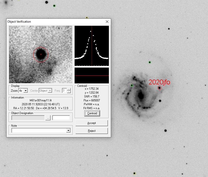
M61 with its new supernova - 8 x 600 seconds.
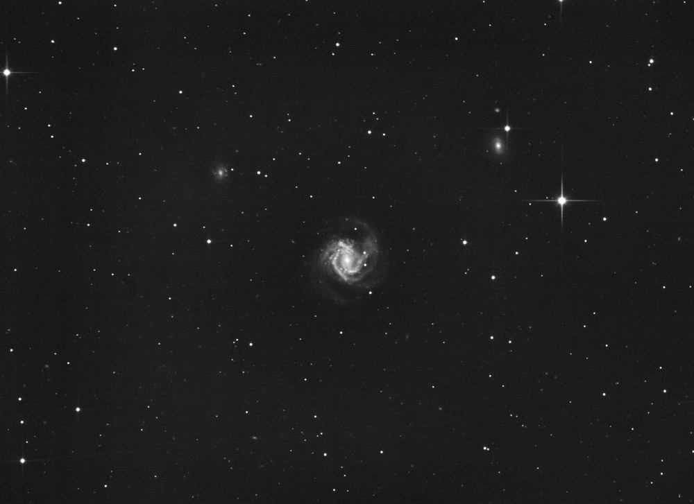
The SN is at magnitude 13.9
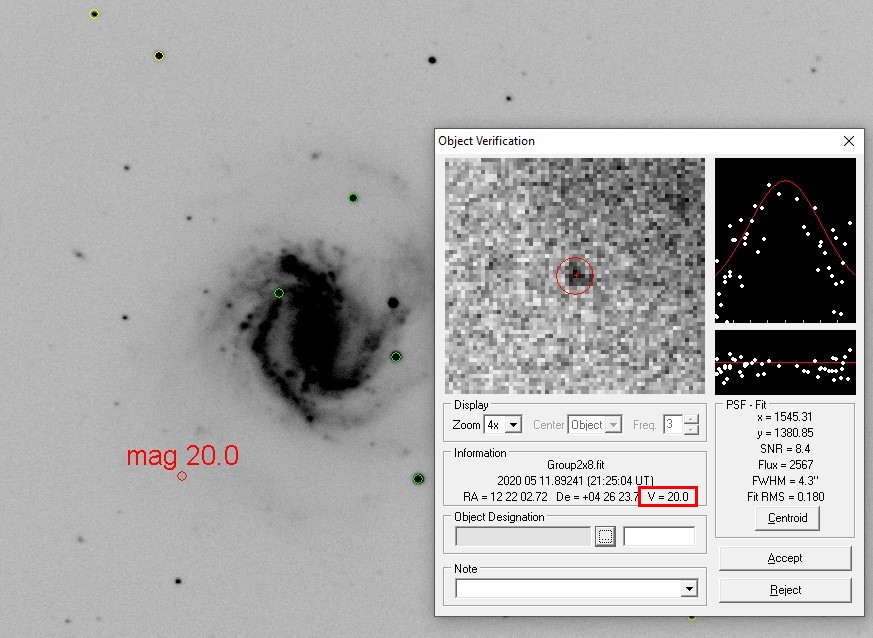
It would appear that the scope can get down to magnitude 20.
The 8" struggled at mag19.0.
May 30th
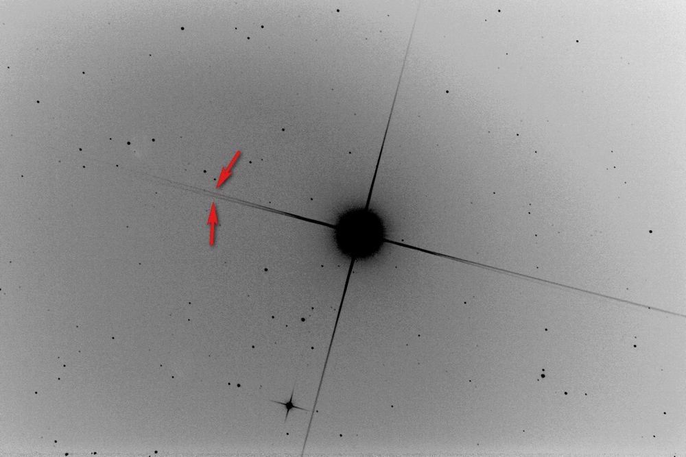
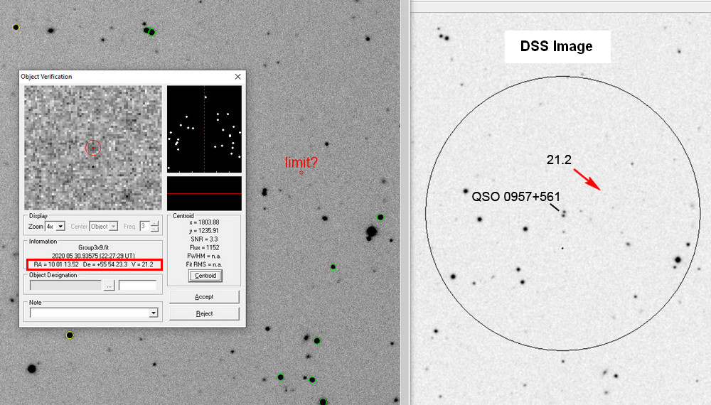
On a tip from Mike Merrifield I had a go at the gravitationally lensed quasar - QSO 0957+561
This is 8.7 billion light years away. At magnitude around 17 this was not difficult, but I checked the surrounding area.
There is an object that is visible on my image and the DSS image.
Astrometrica measured the magnitude at 21.2 which would be a new magnitude record for me.
The image is 9 x 600 seconds.
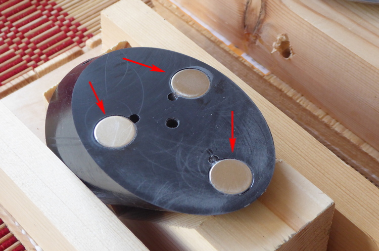
Diffraction artefacts
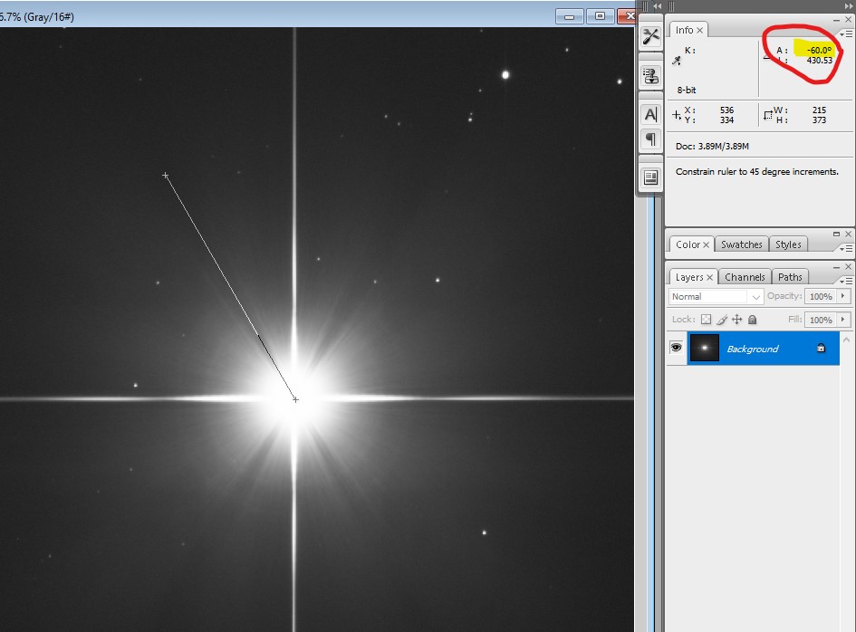
During testing I noticed that bright stars had an unusual diffraction pattern.
The pattern was symmetrical, which was a relief, as some scopes tend to make lopsided bright stars.
There appeared to be rays at 60 degrees to the horizontal.
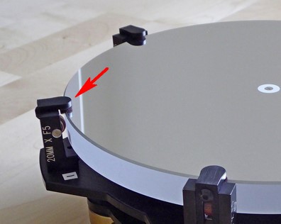
After checking the light path for any protuberances that could have caused this,
the source was tracked down to the six small retaining clips that hold the
primary mirror safe in the cell if the scope accidently points downwards.
I ran a simulation to see what the theoretical output should be:
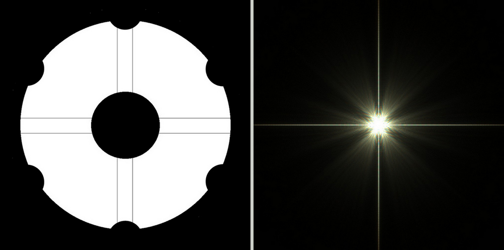
Clearly if the image was rotated 90 degrees, the diffraction effects would match.
In reality only 4 of the 'rays' are seen as 2 are masked by the bright diffraction spikes.
May 15th 2021
The scope performed well but for one problem. Focus. The plastic tube is very susceptible to changes in temperature,
requiring refocussing after every couple of images.
The 8" carbon fibre scope was rock steady, and usually needed to be focused only once per session.
I bought a custom made carbon fibre tube - same diameter but a cm or two longer.
It is a double walled foam filled tube and is VERY rigid.