| Pulsar 2.7 meter Dome Automation |
| As time progresses, the mount rotates the telescope to follow the stars. An observatory is marvellous for housing a permanent installation, but it is amazing how often you have to nudge the dome around on its tracks to keep the aperture neatly in front of the telescope. A series of long exposures during astrophotography often sees the astronomer sitting comfortably indoors while the camera and related equipment takes frame after frame. How do you know if the telescope view is obscured? | ||
| Complex systems
exist that employ a program like Maxim to calculate where the aperture
should be and then send appropriate Ascom-type commands to a motor that drives
the dome around. A simpler system might be to use a magnetic or Infra-red
sensor to determine when the dome needs to be rotated. I purchased a Sharp GP2Y0A21YK proximity sensor. This is a simple device with three leads: power supply, ground and signal. Infra-red light is emitted and any reflected light is detected. The voltage of the output signal is proportional to the distance between sensor and reflecting object. With a 5V supply the output varies between ~0V to ~3.9V. The sensor will be attached to the front end of the telescope. When pointing through the middle of the aperture no infra-red will be reflected, but as the edge of the aperture starts to intrude, a signal will be reflected. The output was connected to an analogue to digital (adc) convertor pin on a Picaxe 18X. Some simple code was used to make a buzzer beep if the value exceeded a certain value. As the distance between scope and dome decreases, the nature of the beeps changes, becoming more urgent. When a limit is reached the Picaxe sends a signal to a motor controller that drives a car windscreen wiper. First tests show that the idea is feasible. This video |
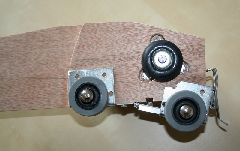
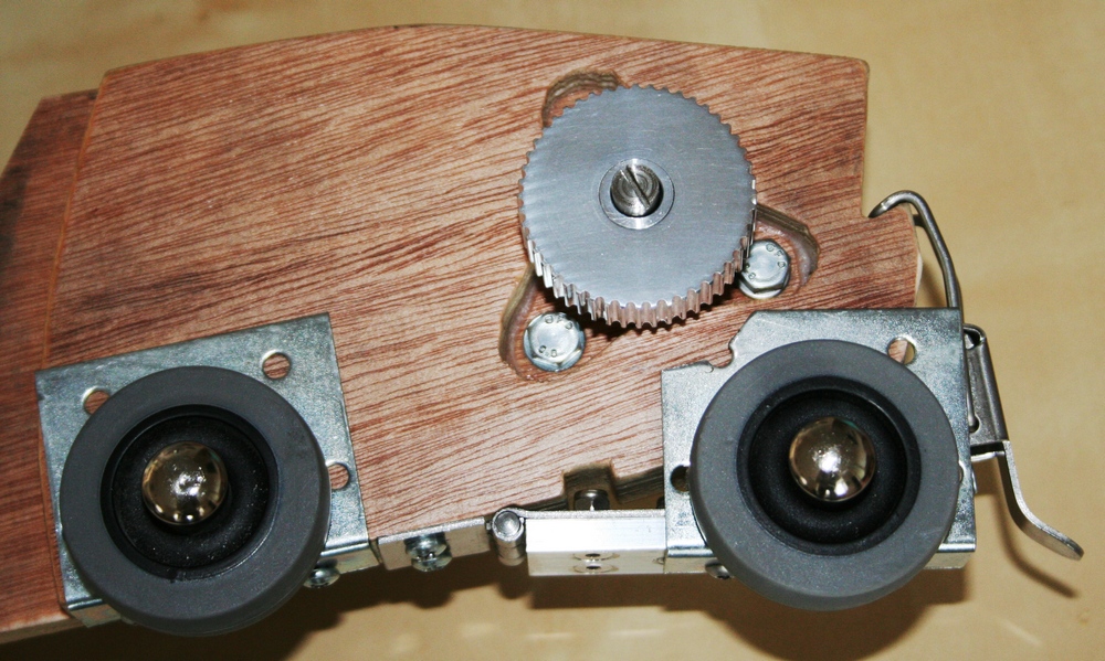
| This is the motor unit showing the rubber drive wheel and the two
idler wheels that will keep the rubber wheel in firm contact with the
track. One idler wheel is on a hinged arm with a quick release mechanism to allow dome rotation to be done by hand. |
|||
 |
|||
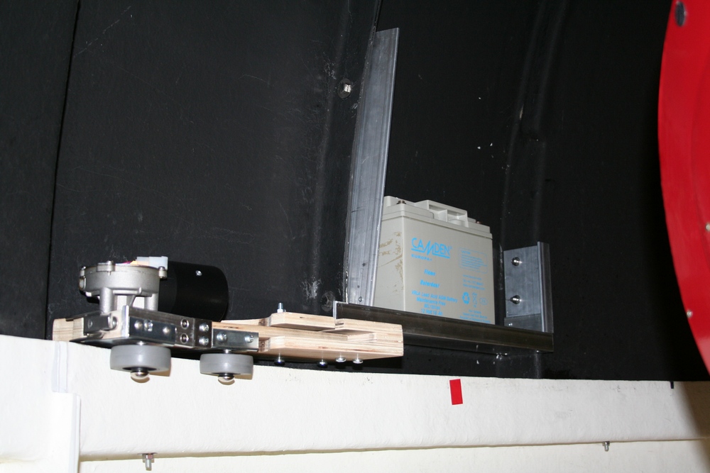
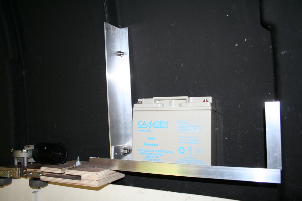
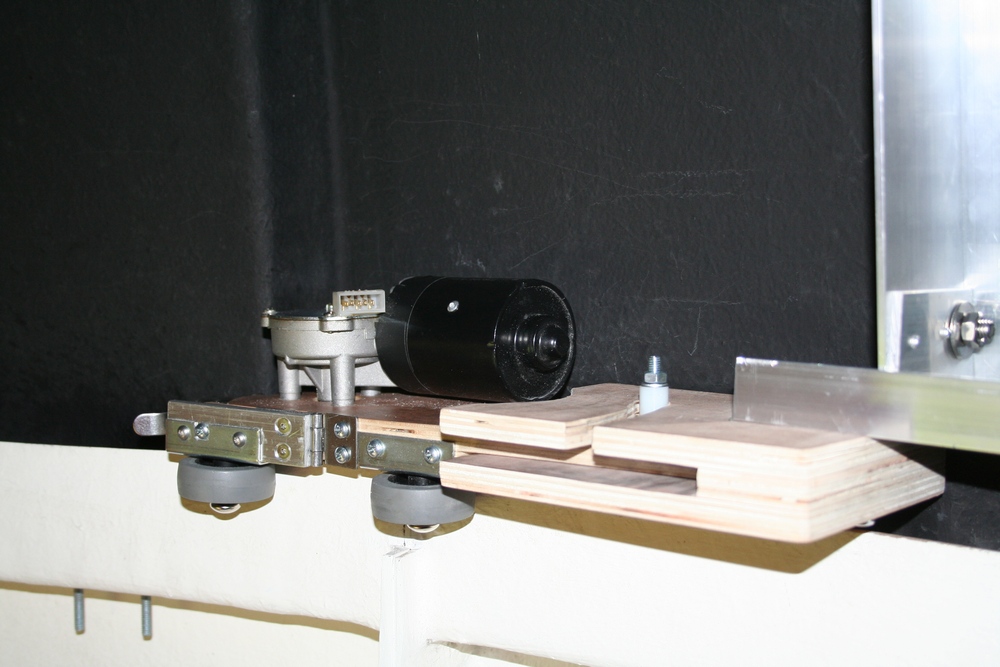
4th July 2011 Aluminium bracket now made and fitted to the interior of the dome. The bracket holds the 12V battery and supports the motor. |
|||
 |
|||
 |
|||
 |
|||
| Quick release latch in open position |
|||
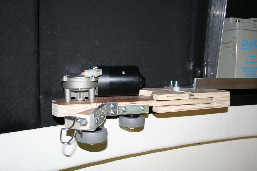 |
|||
| Quick release latch in closed position |
|||
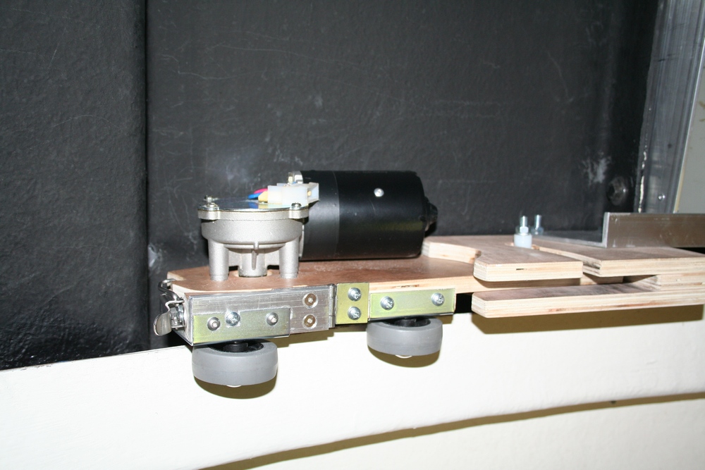 |
|||
| One complication is that at each join in the fibreglass segments there is a raised section that can interfere with the motion of the motor assembly. These will have to be smoothed off. | |||
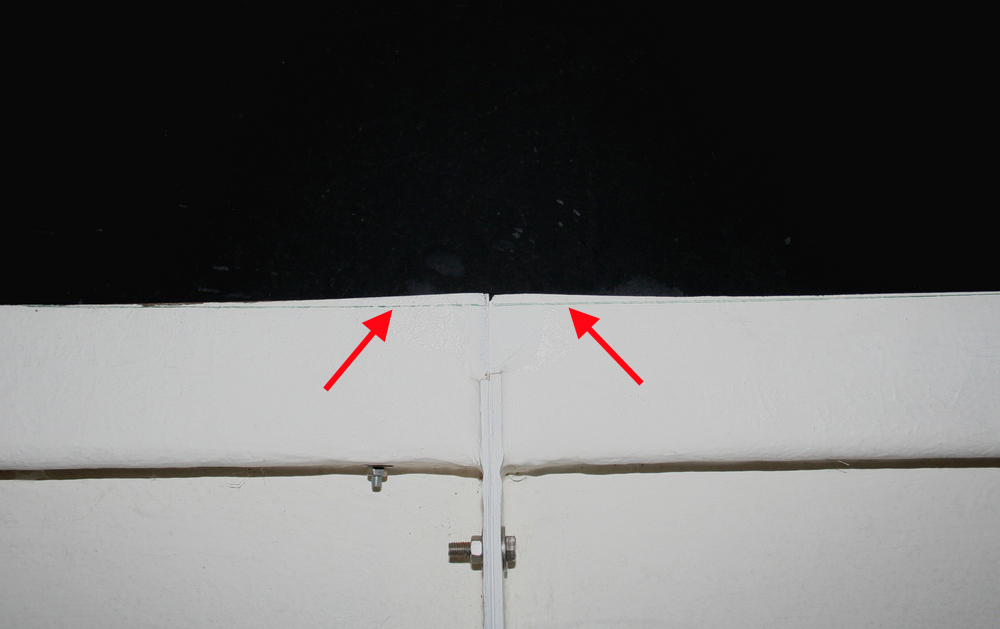 |
|||
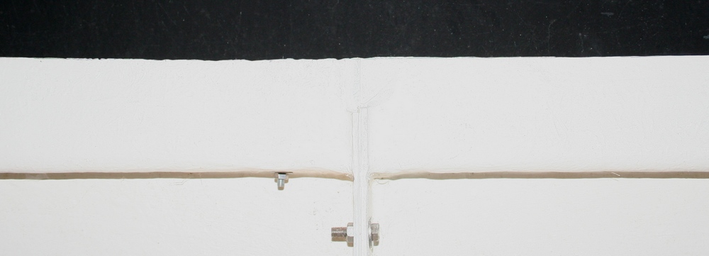
| Picture below shows the offending bump removed. I first tried
using a plane. Not easy on fibreglass. Then a Dremel with a metal cutting bit.
Hard to control and masses of dust. Then I tried a hacksaw. Not enough distance available to get a to and fro action. I then tried the Dremel with a miniature silicon carbide cutting disc. Perfect! It cuts smoothly and quickly and there is less dust. I used a vacuum cleaner held near the cutting disc and the dust problem was gone. The other three joins are much smoother than the first one. |
|||
 |
|||
7th July The rubber wheel does not provide enough grip to rotate the dome efficiently. It works, but there are times when the wheel slips, so this method is now abandoned. This company supplies timing belts in lengths up to 50 metres, so I have ordered 8 metres, and a suitable pulley. This will give a much stronger grip, and should be able to rotate the dome smoothly. 12th July At the 4 joins the fibreglass is thicker, something like 6 - 7mm. Other places are closer to 4mm so each join has to be thinned down a bit. 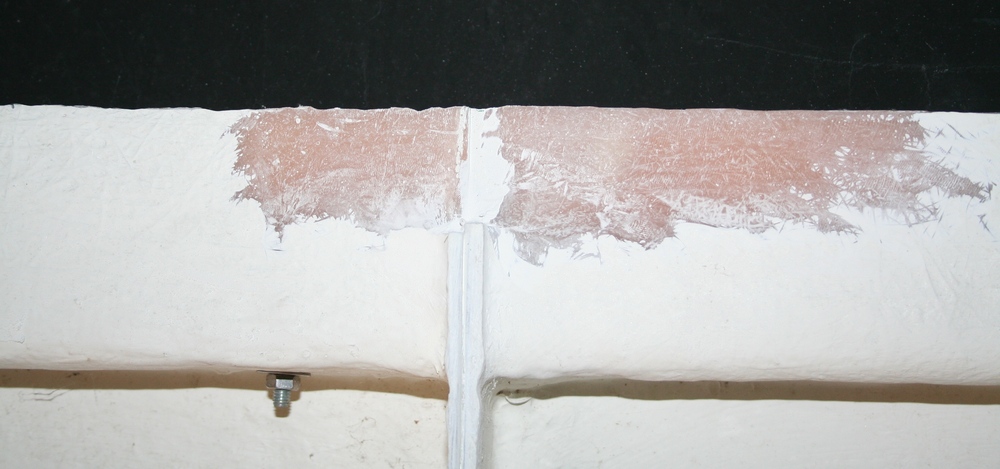 |
|||
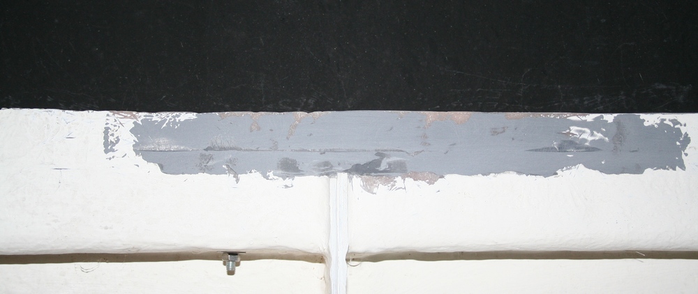
| Filled in with car body repair epoxy and smoothed. | |||
 |
|||
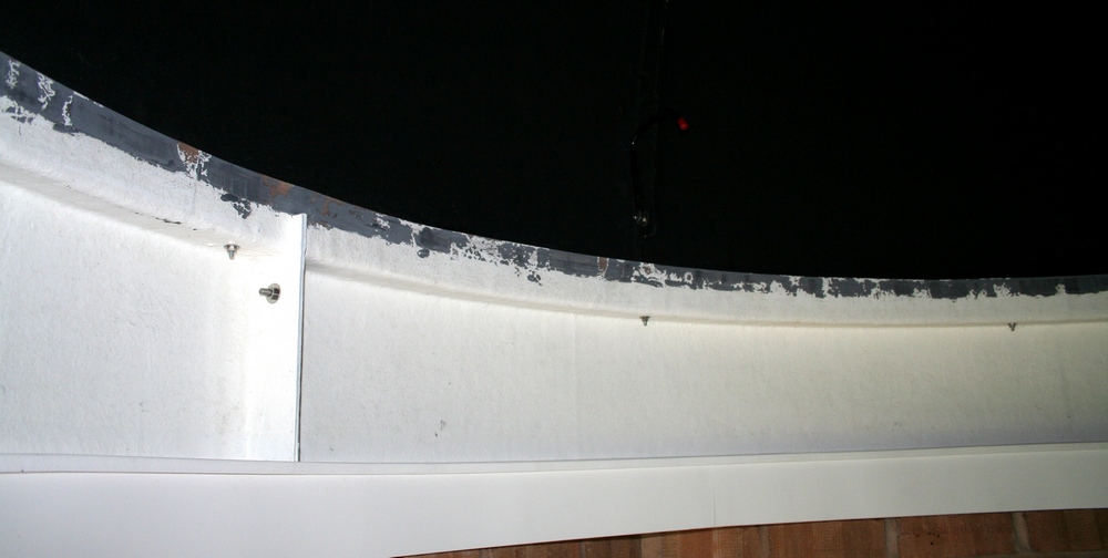
| The inner surface of the fibreglass was rough and dimpled - to ensure smooth running I filled and sanded the whole track. | |||
 |
|||
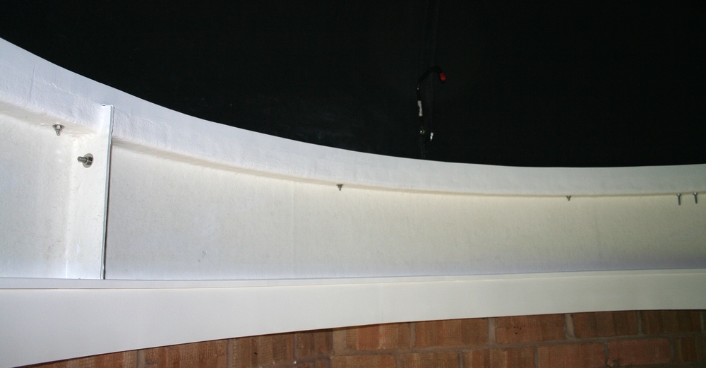
| ... and with a couple of coats of paint. | |||
 |
|||
8th August 2011 The rubber wheel now replaced by a timing belt pulley. Rob Januszewski at Epsilon Telescopes made the central locking shaft to fix the wheel to the wiper motor. |
|||
 |
|||
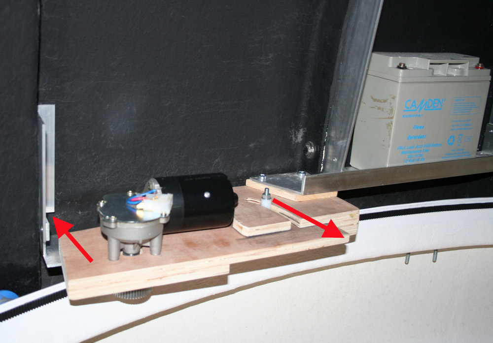
The timing belt pulley runs on the inside of the track. This is because it will be much easier to glue the belt on the inside. At present there is only one idler wheel, running on the outside of the track. The motor assembly pivots around the idler wheel, and there will be two tension springs in the positions shown to keep the pulley wheel firmly against the belt. Trial runs using elastic bands show that this will work. |
|||
 |
|||
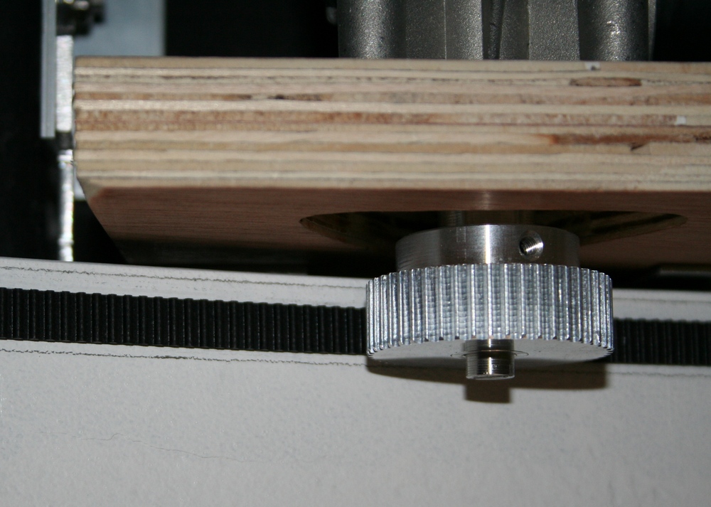
12th August 2011 Close up of the belt and pulley wheel. The belt was glued on with superglue which sets alarmingly quickly. There is almost no time to reposition the belt. |
|||
 |
|||
| This video
|
|||
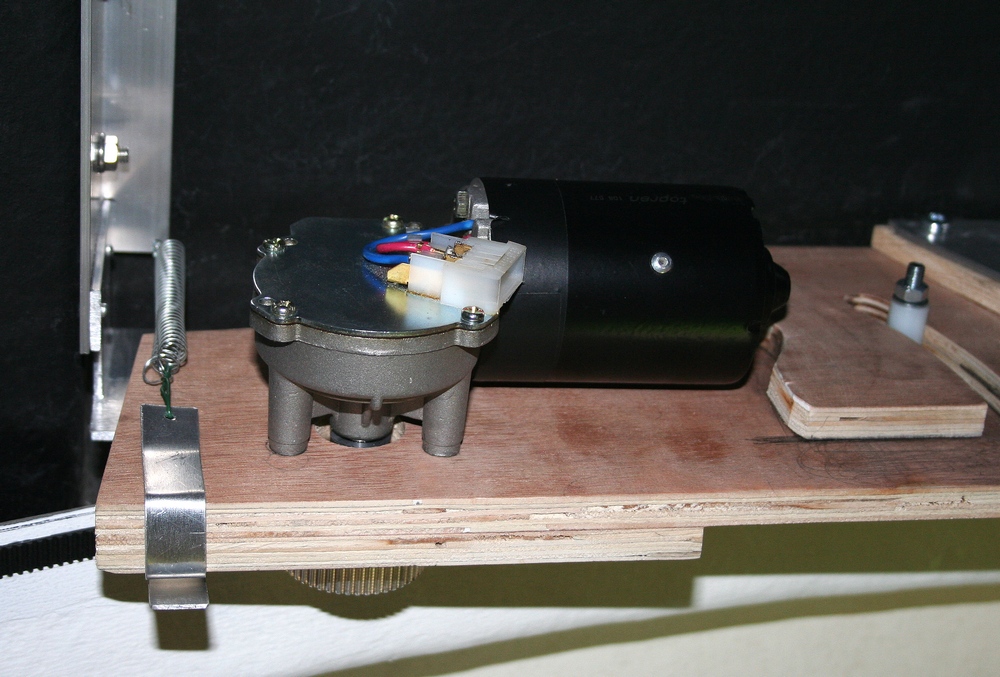
13th August 2011 Tension springs at the left. The aluminium strip folded over the plywood can easily be slipped off to allow rapid slews by hand. (I had intended a second spring at the right hand side but it may not be necessary). |
|||
 |
|||
| This video
|
|||
28th August 2011 A small job to make life easier. The shutter opening rope often slipped off the pulley. This aluminium attachment keeps it neatly in place. |
|||
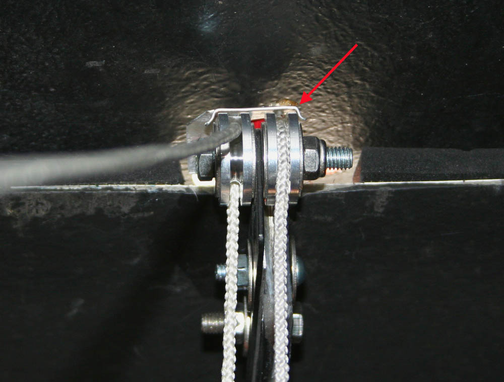 |
|||
Note the extra bolt. Only one is supplied and it is impossible to tighten it up enough to avoid movement. 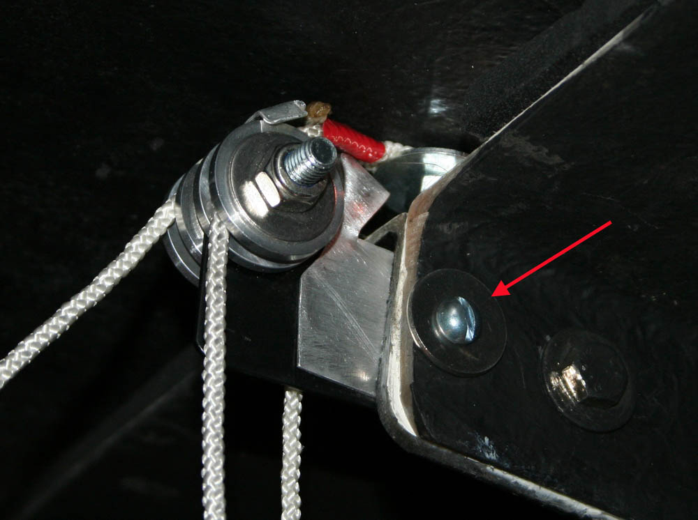 |
|||
4th September 2011 This is the first try at wireless remote control. The receiver is from a toy car, operating at 40 MHz. When it gets a signal from a joystick control, or the IR sensor, it will activate the motor. The device does what it is supposed to do, but the range is limited, and even a metre or two distance between transmitter and receiver causes intermittent performance. I will move to a 433MHz system with a controller normally used to open garage doors and the like. |
|||
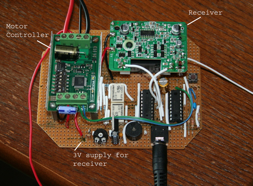 |
|||
In the meantime, I have cobbled together a simple timer that will rotate the dome a small amount every 10 minutes or so. The box to the left of the battery contains the electronics. The toggle switch sets the direction of rotation, and the dial allows the speed to be varied, according to where the telescope is pointing. Experiments are now under way to determine how often the dome should be moved, and how far each step should be. |
|||
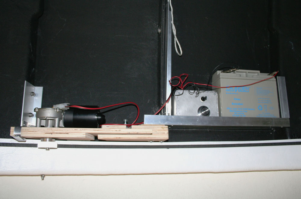 |
|||
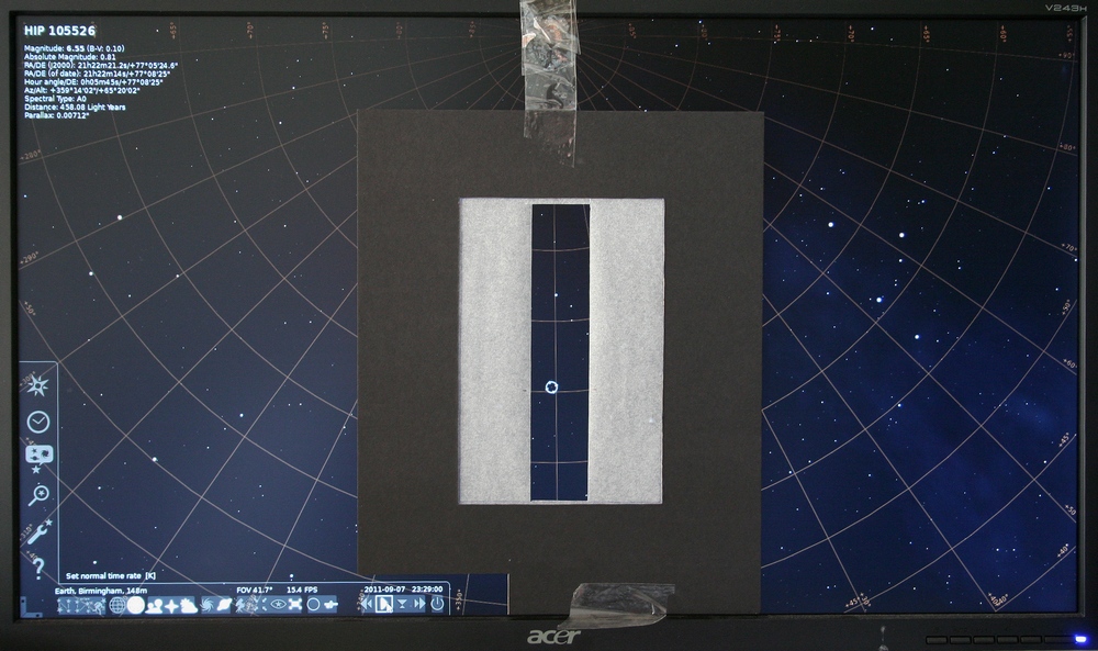
How fast should the dome rotate? A first try at finding out involved cutting a slit in a paper sheet to represent the dome aperture, and timing how long a star in the planetarium software Stellarium would take to cross the slit. This was not done in real time but by observing the time reading on the screen, and the star motion could be accelarated. Readings obtained were accurate enough, but to cover the whole sky would require many hours work. Places where the star crosses the slit at a steep angle were also difficult to evaluate. |
|||
 |
|||
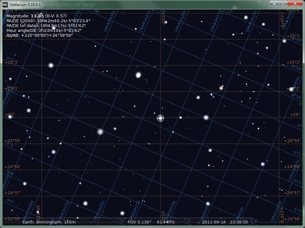
The next attempt also used Stellarium, which allows both an equatorial grid and azimuthal grid to be displayed at the same time. In the picture below the brown grid is Azimuthal and the blue grid is equatorial. The star is positioned at 220° azimuth and 25° altitude. The precise declination of the star is displayed. |
|||
 |
|||
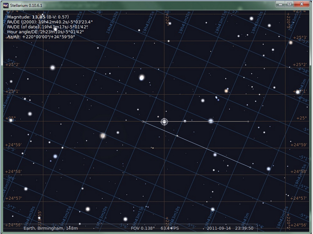
A screen grab pasted into Photoshop allows angles to be measured. In this example, for my latitude, a star at Az 220° and Alt 25° is seen to have a declination of -5° 01' 42" and is moving at 23.1° to the horizontal. The horizontal speed = maximum sidereal speed x COS(-5° 01' 42") x COS 23.1°=13.74 arcseconds per second. This method is far more accurate than the first, but is still very time consuming. |
|||
 |
|||
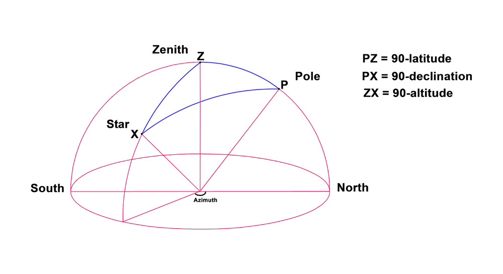
The ideal solution would be to generate all the angles mathematically. Fortunately the spherical trigonometry involved is not too difficult. In the diagram below the blue lines demarcate a spherical triangle which obeys a simple cosine law: cos(PX) = cos(PZ)*cos(ZX) + sin(PZ)*sin(ZX)*cos(azimuth) |
|||
 |
|||
An Excel spreadsheet allows all the angles to be speedily calculated. It is then quite straightforward to calculate a conversion factor for how to set the dial on the motor control box. When the star motion is almost parallel to the dome slit, or very slow near the Pole, a value of 1.0 is given. In these positions the dome motor could be switched off. The Eastern hemisphere has identical values. First trials worked very well and the dome has kept pace with the telescope for over 3 hours on one motor setting. |
|||
 |
|||
Although it is most unlikely that anyone would aim an astronomical telescope at the horizon, it is interesting to note that in that position the horizontal motion of the stars remains constant for the whole 360 degrees. In the above example for altitude = 0 the motor setting is 8.5 for all positions of azimuth. |
|||
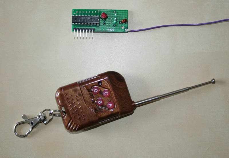
| 17th September The 433MHz transmitter and receiver arrived (£8.90 from Singapore). The right hand pin is Vcc, 3rd from the right is ground. When a button on the transmitter is pressed whatever is on the 2nd pin is transferred to one of the output pins. Connecting the 2nd pin to Vcc via a resistor is an easy way to get a logic 1 transferred to the outputs, which is easy to interface to the Picaxe microcontroller. |
 |
||
|
See this
video
|
|||
| 19th September The completed installation. Wiring tidied up, and an ON/OFF switch provided at the right hand edge. No more danger of hooking up the crocodile clips the wrong way round... |
|||
 |
|||
28th September The latest addition to the hardware is an Infra-red security camera. This is wireless and runs at 2.4GHz. The telescope and dome aperture can easily be seen from indoors, and the 433MHz link enables the dome to be rotated when necessary from the comfort of my study. 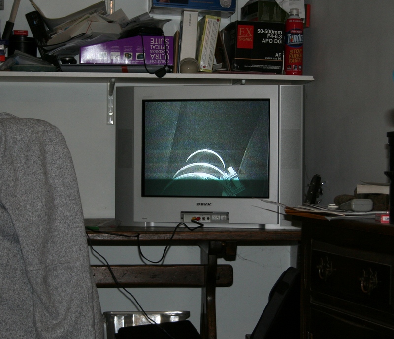 |
|||
4th October There is a problem with using an infra red camera to monitor the dome position - the infra red is picked up by the imaging camera and produces some nasty gradients. This can be seen at the right hand edge of this image of the veil nebula. 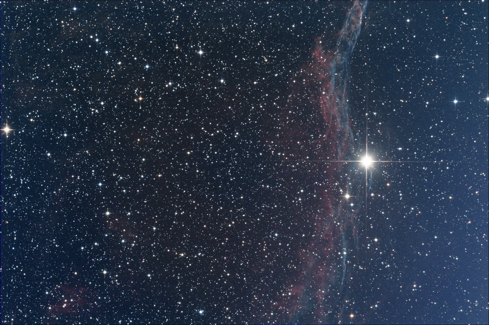 I have tried blanking off some of the IR LEDS, but if there is so little IR that no gradients are produced, then there is not enough light to be able to see the telescope and dome. The answer may be to have a system that can switch the IR camera off while imaging and turn it on at intervals to monitor the dome. This will require additional remote capabilities and may not be worth the effort! Test image. Most of the light causing the smeared gradients is getting into the telescope through the vent at the rear. This image is 10 minutes exposure with the dome shutter closed.  |
|||