| Stepper motor focus control |
The new focuser for the 10" scope has a 10:1 fine control, and very little torque is required to rotate the fine control knob. It should be quite a simple matter to construct a stepper motor control to do the focussing, thus removing vibration from the telescope which is always a problem when you try to focus by hand. There will also be a quantitative measurement of the focus position which will be of great value when doing Bahtinov and Carey mask experiments. A small but sturdy stepper motor was purchased, and a Picaxe microcontroller was used as the basis for the electronics. |
|||
Picaxe board on the left, L293D motor driver centre. 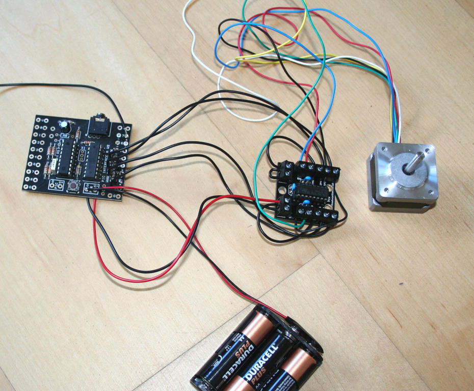 The Picaxe development board is easy to use. A connection to a computer USB port allows the programming code to be installed in the Picaxe chip using a very simple BASIC type language. The stepper motor had 6 wires of which only 4 are needed, but the people who frequent the Picaxe Forum were incredibly helpful in answering my dumb questions, and I eventually got things wired up correctly and the motor responded by rotating on command. |
|||
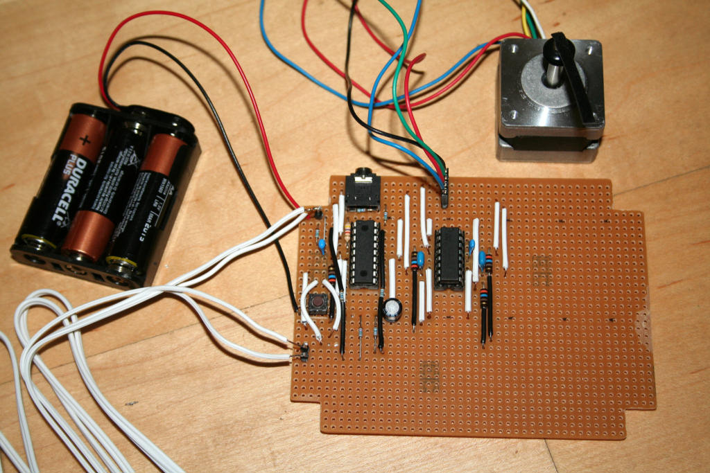
The stepper motor has 200 steps per revolution. Some experimentation enabled the motor to be half stepped so that 400 steps per revolution was possible. This rotation coupled directly to the focus knob will give 3 microns movement per step which is certainly a much finer control than could ever be obtained by hand. The picture below shows the electronics taking shape on a piece of circuit board |
|||
 I had initially considered wiring up 7 segment LEDs to give a readout of focus position, but the Picaxe Forum suggested using an LCD display. One was obtained via Ebay for less than £5. Hooking the display up to the Picaxe involved quite a bit of 'one step forward and two back', and a microscopic blob of solder on the circuit board that was shorting two tracks took several hours to find. But eventually the display started working, only to switch off as soon as the stepper motor was activated. Again, several hours elapsed before it became clear that the problem was simply due to a low battery voltage! If the voltage supply is inadequate these LCD displays respond by shutting down. |
|||
 |
|||
| The
picture above shows the display with a rapidly changing count hence the
disturbed digits to the right. The temporary red LED shows a pulse when the
display is being sent data. The jack plug connected to the PC for programming
can be seen at the rear of the circuit board. Below is the project squeezed into a case. The left hand toggle switch rotates the stepper at 'fast' speed, and the right hand switch is 'slow'. On switch on the focus number is set to 1000, and then each subsequent step of the motor is displayed. |
|||
 |
|||
| The stepper motor is now in its case, which is simply a length of 50mm square aluminium tube. Plastic end caps for the tube neatly close the box.  |
|||
| A small grommet with the same diameter central hole as the motor shaft is glued on and a small rubber sucker is glued to the grommet. Initial tests show that friction between the sucker and the focus knob may be sufficient to drive the focuser. If not, some adhesive will be employed.  |
|||
| The focuser attached to the telescope. It was a bit nerve wracking drilling holes in the side of the telescope but luckily all the holes got drilled in the right places. The system works perfectly! When the stepper motor is switched off the focuser can be turned by hand, which in turn, rotates the stepper motor. When power is applied the motor rotates the focuser under command of the two toggle switches. Some care in adjustment had to be made to get the axis of the motor lined up accurately with the axis of the focus knob. Plastic shims were inserted between the motor case and the scope tube to enable this to be done.  |
|||