Zambuto Mirror - Part 2
24th March
First light!
I observed Jupiter for some time. Ganymede was approaching transit.
When the scope had cooled down the image was superb.
Using a 2.5x PowerMate the Great Red Spot was easy to see.
I have never seen the GRS visually before.
After Jupiter I took a few test images with the Canon 350D DSLR
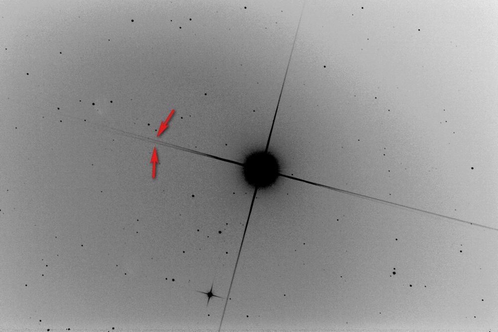
A simple 30 second image of Arcturus.

Negative image.
One set of diffraction spikes is split.
This suggests that the spider vanes on one side of the secondary are not in line with
those on the opposite side.
The final version of the scope with the carbon fibre tube will need some form of
adjustment so that the spider vanes can be accurately aligned.
This is a simulation showing perfect vane alignment - the centre image shows the diffraction effects when focus is perfect.
The right hand image shows 100micron defocus.
With perfect alignment the out of focus spikes are doubled.

Perhaps two vanes are parallel with each other but skewed?
The in-focus image shows splitting of the horizontal spikes.
The out of focus image shows left hand spikes split, but the right hand set come to a point.

What if two vanes were pinched together at the top?
When in focus the horizontal spikes split into three spikes.
The out of focus image shows left and right symmetry.

An out of focus image.
The horizontal spikes converge to the right, suggesting that I have the 'skewed' situation rather than the 'pinched'.
The trick now will be to figure out which vanes are responsible!
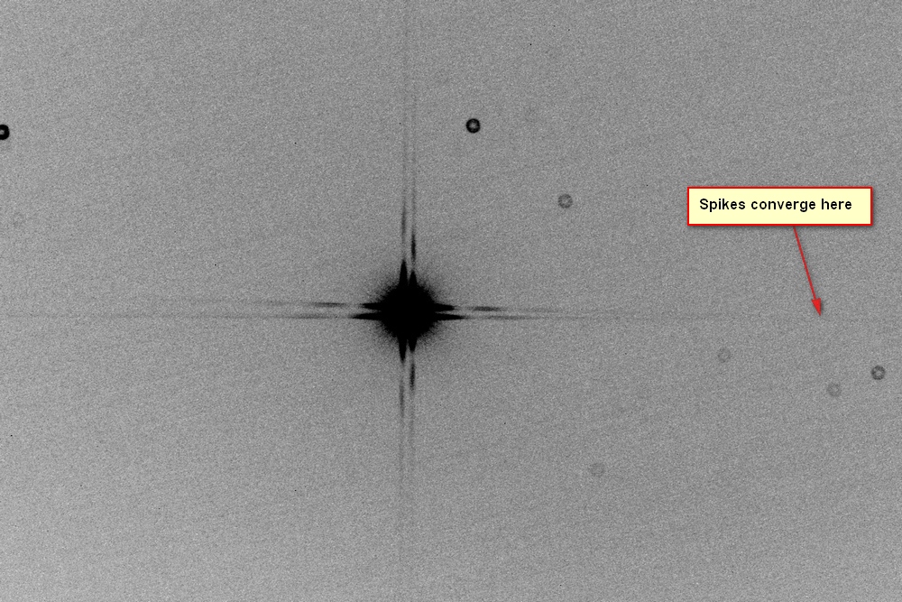
This seems to show the culprit vanes.
The 12 o'clock vanes show a small deflection to the left.

29th March
Carbon fibre tube now ordered from Klaus at http://klaushelmi.de/en/
Specifications are: Length 1300mm, inside diameter 255mm wall thickness 7mm.
The wall is Hardfoam cored with double carbon fibre layers for extra rigidity.
Delivery time is about 3 weeks.
6th June
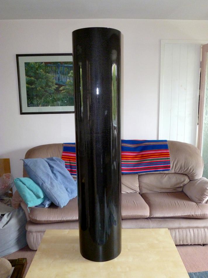
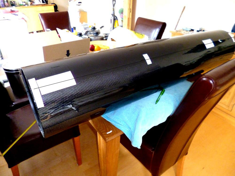
The carbon fibre tube has arrived from Germany:
18th June
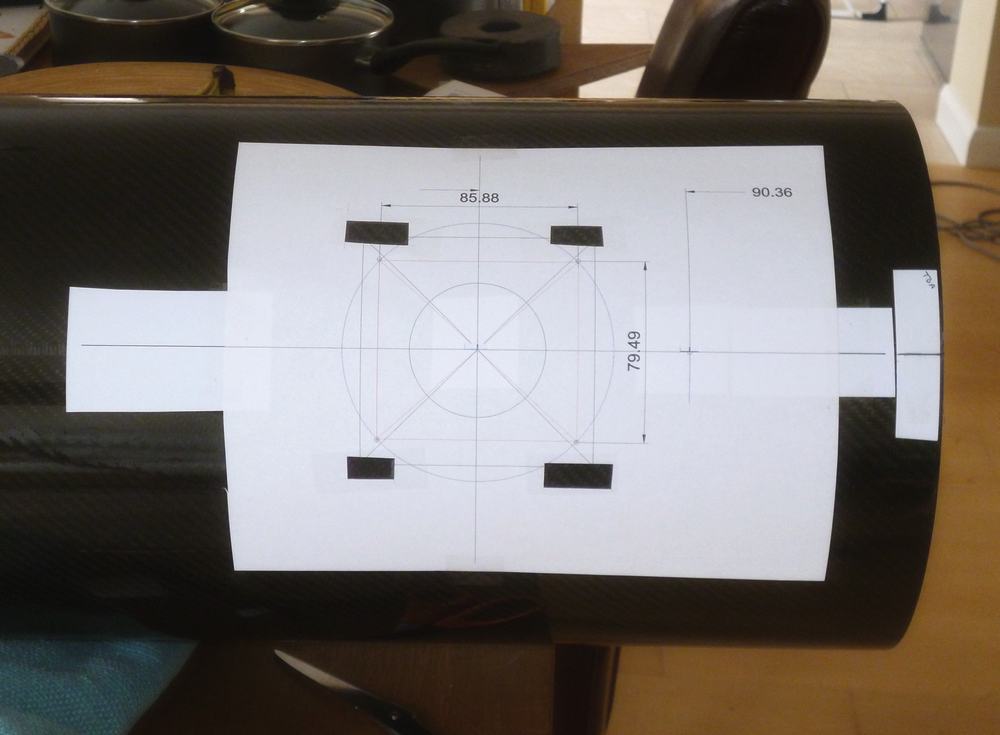
To mark up the tube for drilling the holes I have stuck pieces of adhesive printer paper on it.
I could not find a pen that would write on the surface.
The first job was to establish a straight line along the tube that was parallel to the intended optical axis.
I used a CAD program to draw up a template for drilling the main focuser hole,
the 4 focuser fixing holes and the first of the holes to support the spider.
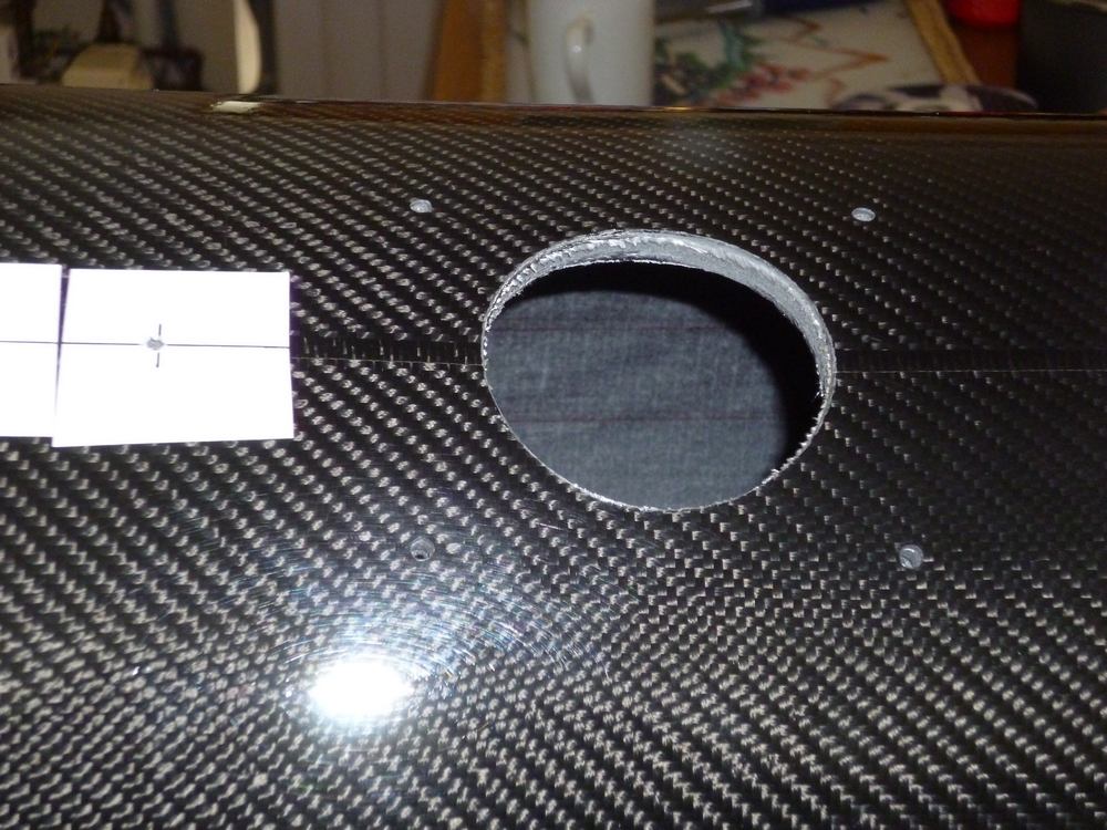
Main focuser hole cut.
(Note double carbon fibre tube construction with foam sandwich).
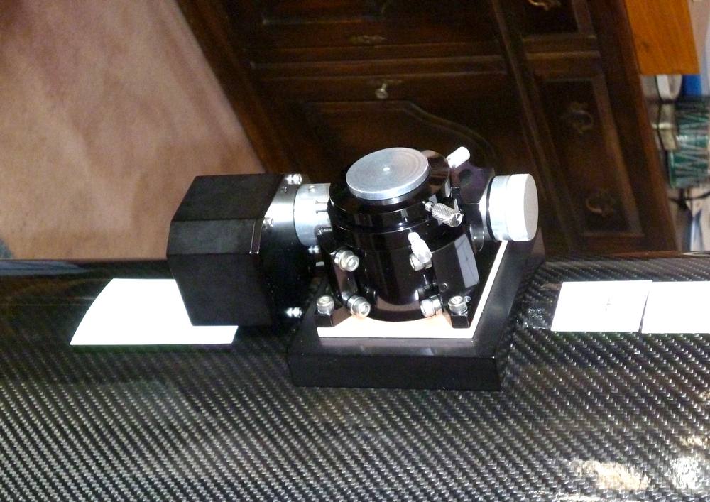
The focuser base fits neatly.

Focuser in place
19th June
Spider and mirror cell holes drilled and everything assembled.
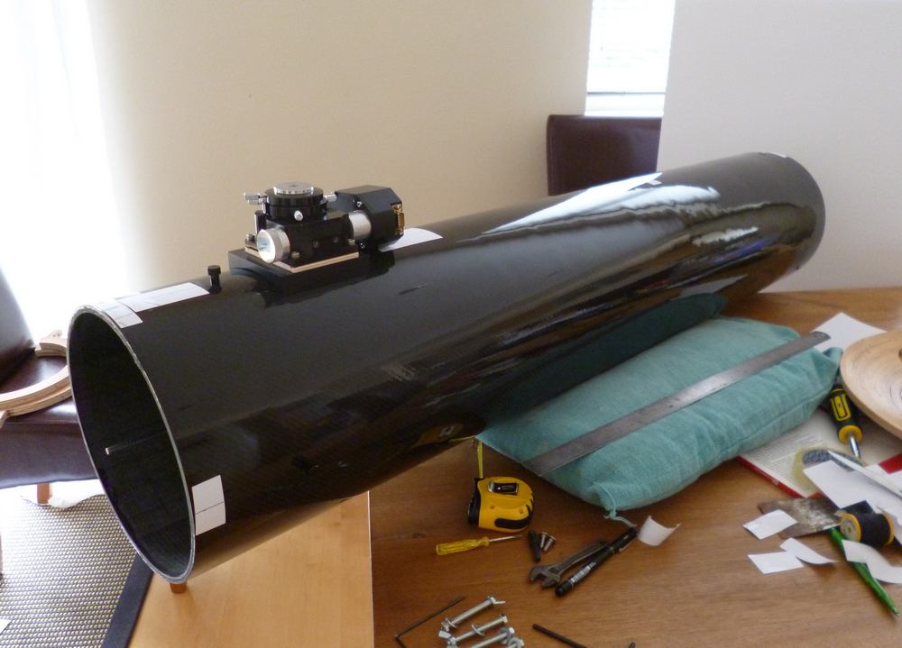

The next job is to get a rough collimation and see if it reaches focus.
The carbon fibre tube has thicker walls than the cardboard tube, so there is room for error.
Good news - focus reachable. Focus is with the focuser tube only a few millimetres from its lowest position, so vignetting will be minimised.
20th June
Stroke of luck. The prototype cardboard tube came with plastic end caps.
They fit the Carbon fibre tube perfectly!

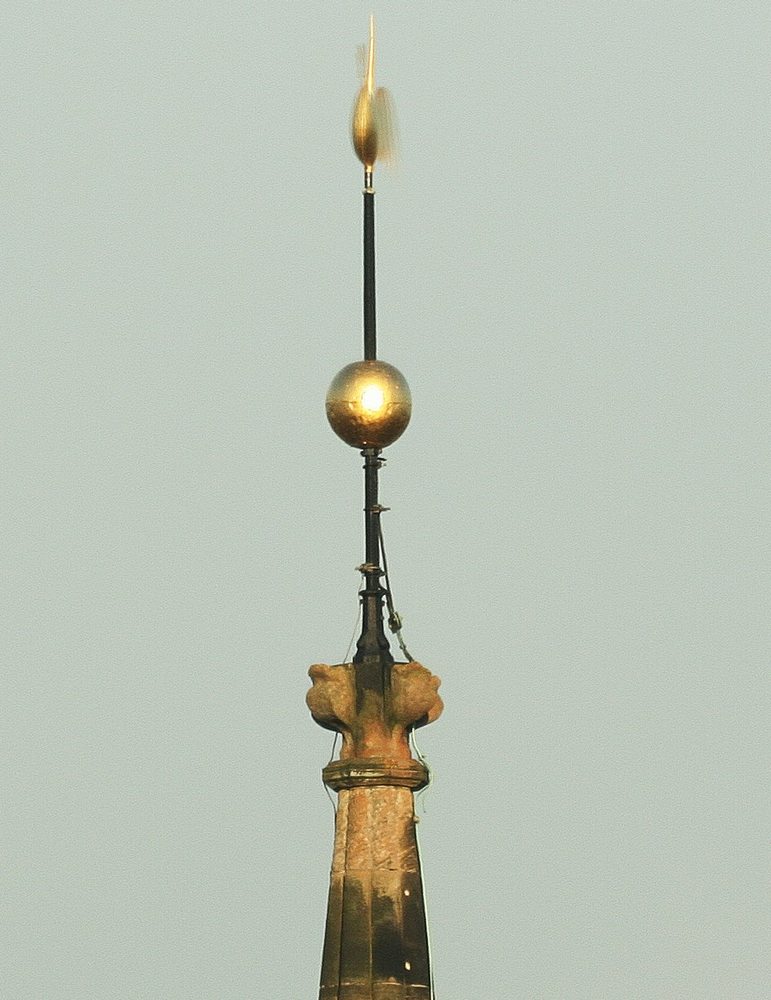
A test image of the church spire.
Seems sharper than any of my other scopes.
22nd June
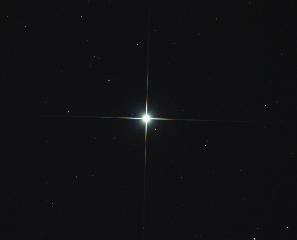
The first test image on a star showed that the spider vanes were not correctly adjusted - diffraction spikes were split.
Some alterations were made and the next image was much improved.
Vega. 10 seconds, Canon 350D DSLR
The scope has been designed with astrophotography in mind.
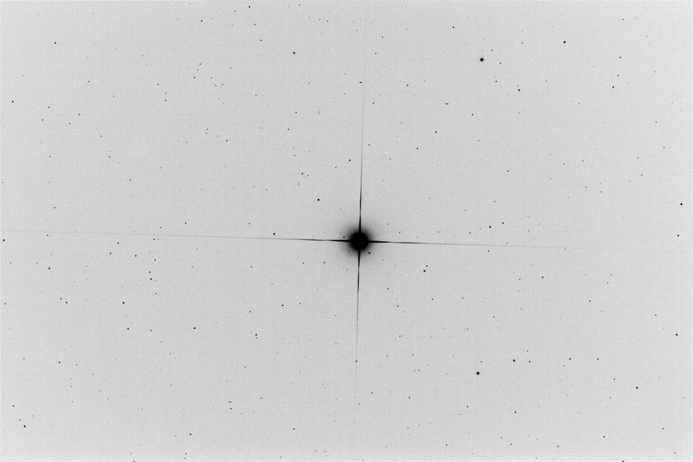
A Baader MPCC coma corrector is used and should produce good pinpoint stars to the edge of the frame.
This is a greyscale negative to show fainter stars. (The CCDchip is 22x15mm in size)
June 24th
The inside of the tube needs to be lined with flocking, which is far more light absorbent than black paint.
Flocking comes in sheets with an adhesive backing. I learned from the 10" reflector
how difficult it is to get this inside the tube without it sticking to the wrong places
and getting numerous folds and creases.
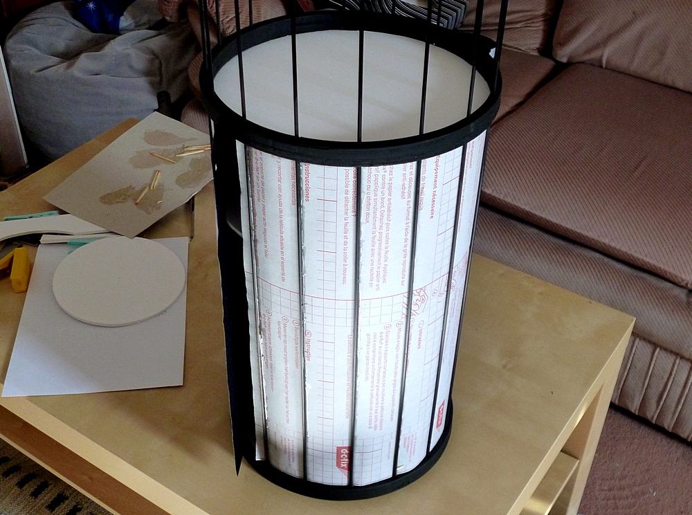
Solution: Make a cage to hold the flocking.

The rings (plywood) will also act as light baffles. The rods needed to be strong but light, so I opted for carbon fibre.
Almost half the cage filled with the flocking material.
White card discs on the inside to hold the flocking nice and smooth,
then Araldite glue along the carbon fibre rods.
July29th
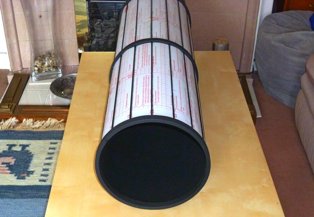
Flocking cage completed
August 2nd
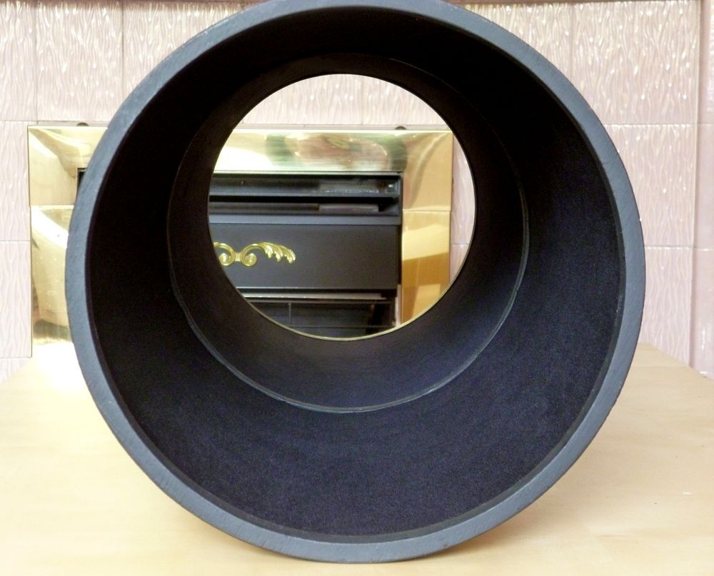
Flocking on either side of central cage in place. The two painted plywood rings arrowed reflect a lot of light.
I might try strips of flocking to cover them. (Or am I being a bit too neurotic?)
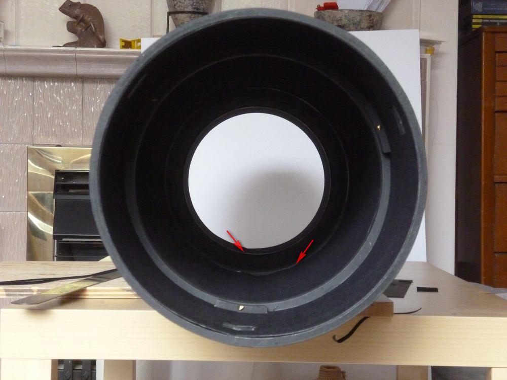
August 2nd
Much improved - the two rings are almost invisible.
(Looking into the tube from the primary mirror end).
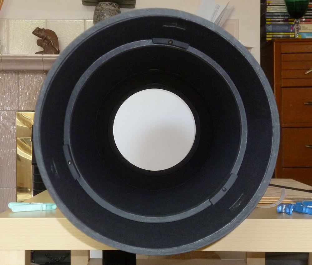
The offending central ring now covered by flocking.
(Looking in from the 'sky' end).
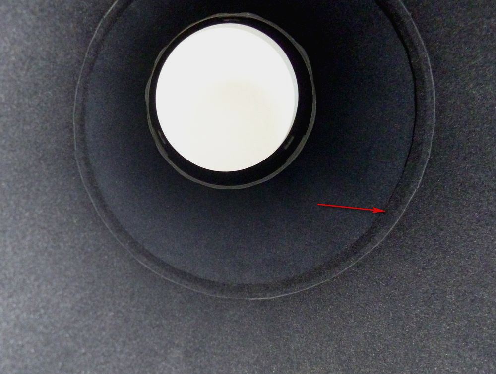
The outermost ring covered by a flat strip of flocking.
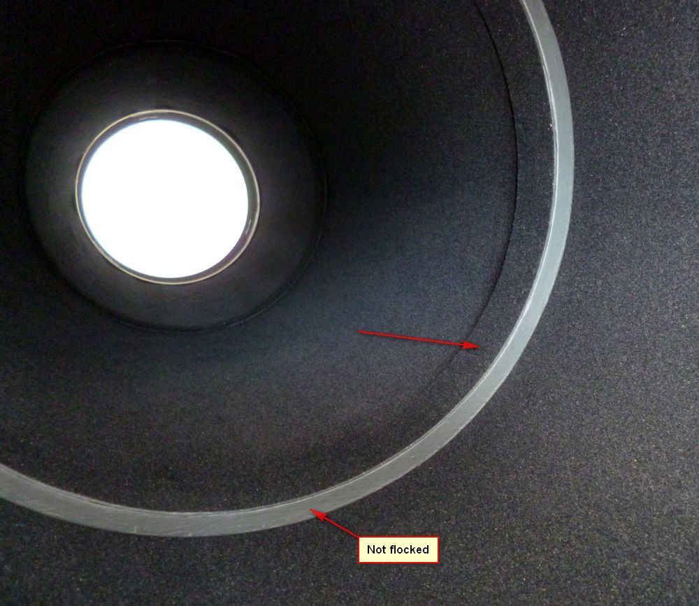
The front face of the ring nearest the sky has not been flocked as it is not visible to the primary mirror.
Stray light from it might hit the secondary mirror but will be very far off the central axis
and should not end up in the camera.
The ring near the primary mirror has not been flocked. Any light bouncing off it will
hit the primary at a shallow angle and should never get into the ccd camera.
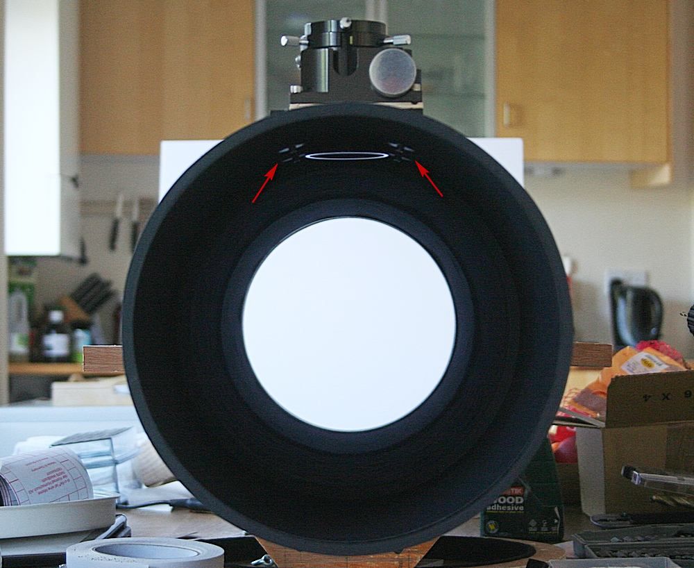
Focuser in place. There are some reflections from the bolts that hold the focuser, and off the underside of the focuser tube.
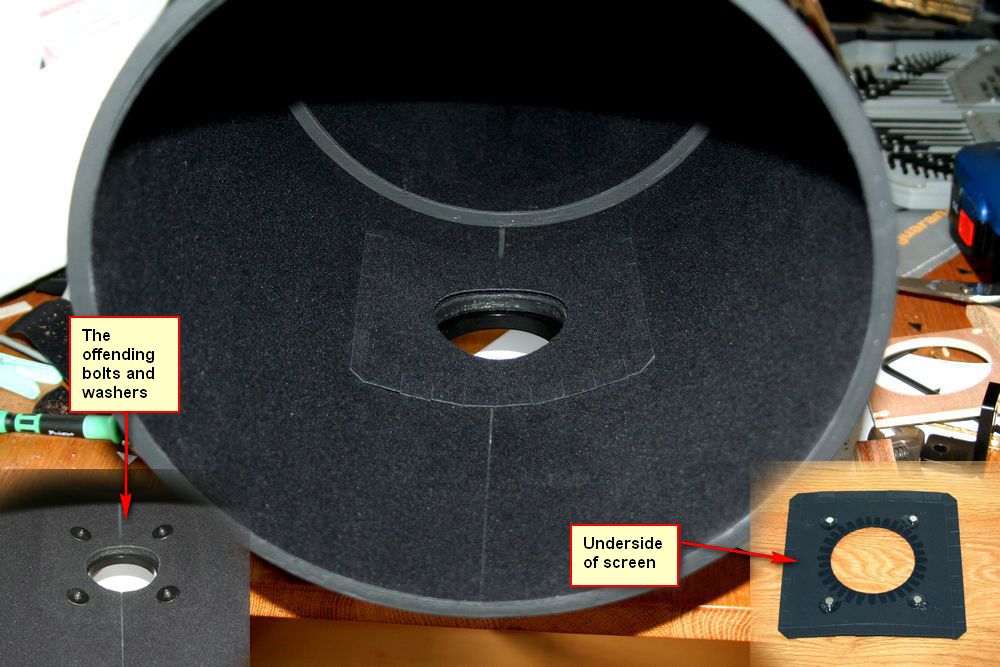
Solution for the light reflecting off the focuser bolts...
A small screen of card and flocking, held in place by 4 small neodymium magnets
which stick firmly to the washers under the focuser bolts.
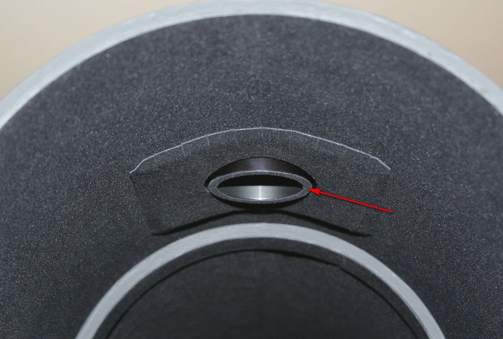
To stop light reflecting off the lower end of the focuser tube, a small ring of
flocking has been stuck on.
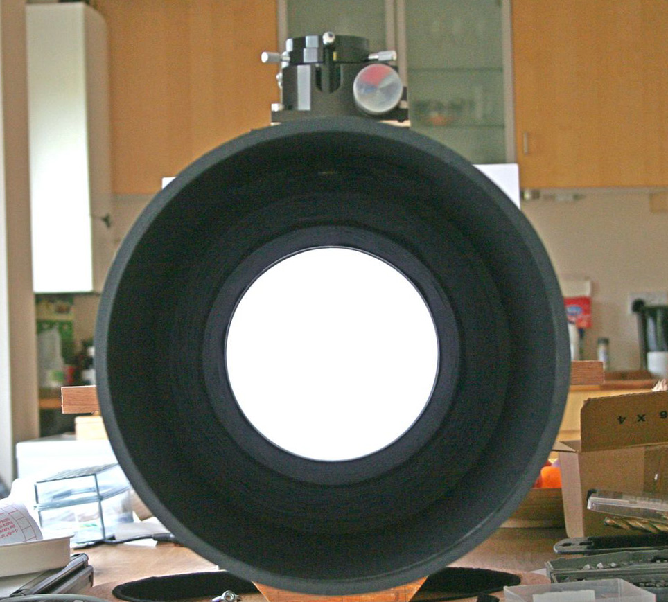
Only the slightest hint of anything visible by the focuser.
This image has been brightened considerably to show the interior of the tube.
August 7th
Fitting the secondary.
The secondary mirror is offset by 3mm, and the easiest way to ensure that the
secondary is correctly positioned is to use a laser and a paper template.
The template has lines to indicate where the optical axis should be.
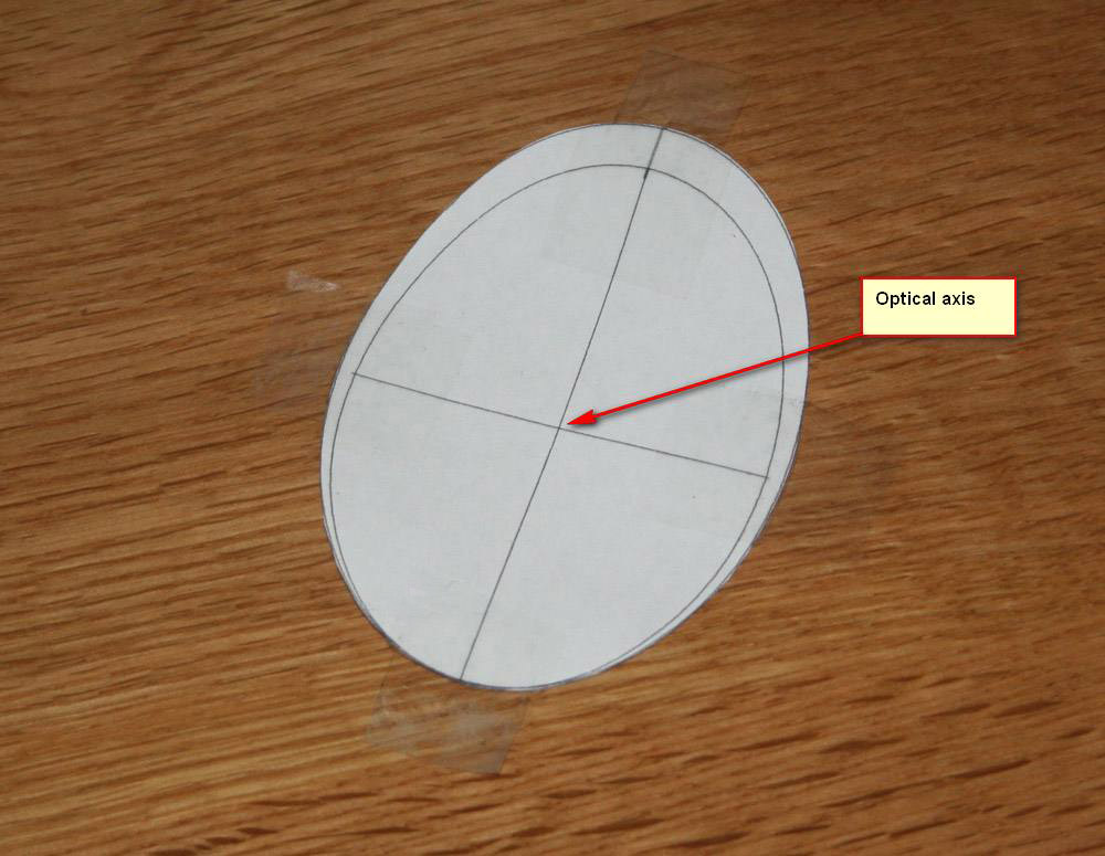
This template is then carefully placed over the secondary and secured with sticky tape.
A laser collimater then shines a laser beam onto the template and the secondary spider can be adjusted correctly.
If necessary the focuser can be tilted a little to make sure the laser hits the right spot.
(An old mirror is held inside the tube to see what is going on).
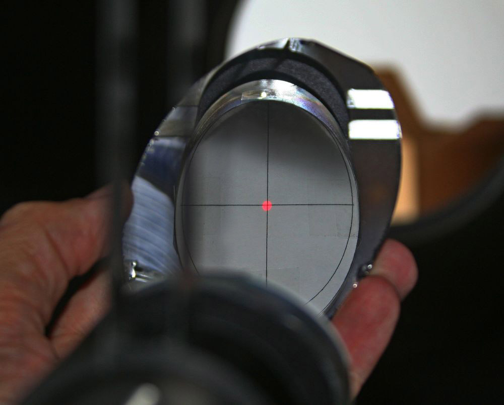
Primary mirror in place and scope collimated.
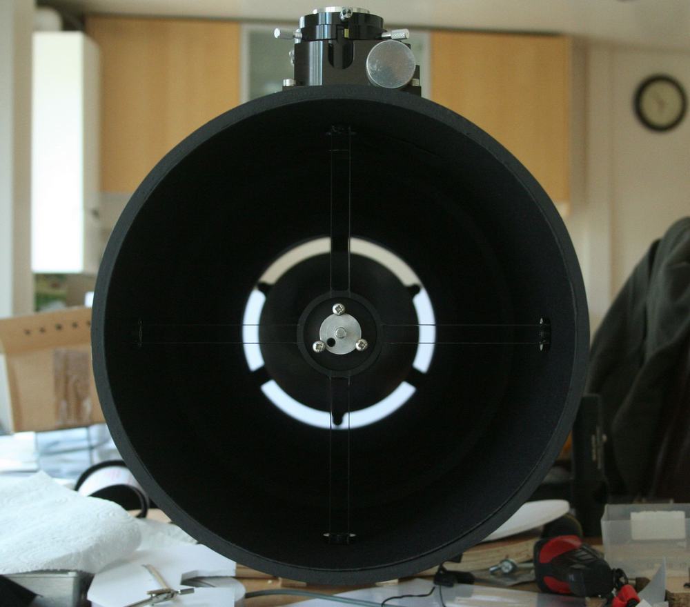
8th September 2014
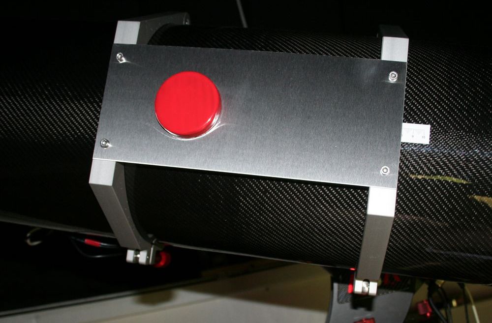
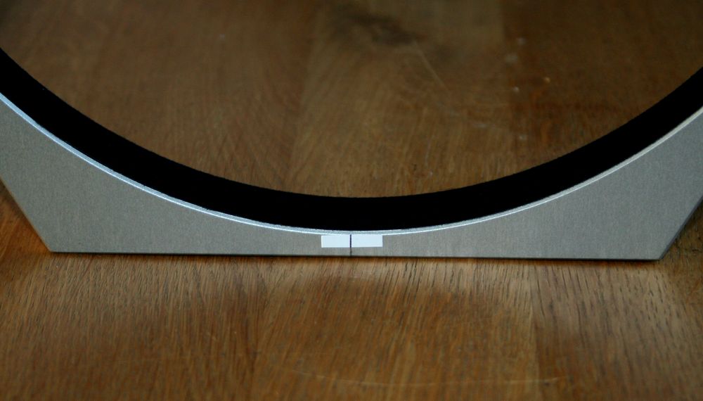
The custom made tube rings arrived from ASA in Austria.
They fit very snugly and the scope/mount system should be extremely rigid.

Marker to show the centre point of the tube rings.
This is used to get the scope tube correctly aligned.
The centre of the focuser/camera axis is lined up with this mark.
This will help in getting images oriented precisely 'North is UP'.
9th September
The new scope is on the mount.
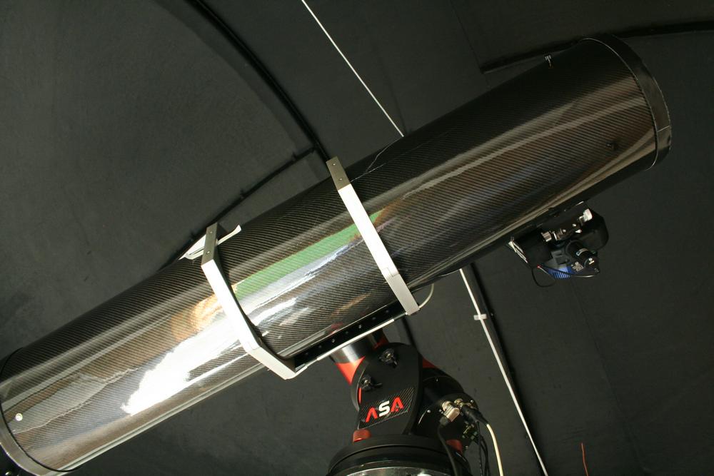
Full Moon hampered testing, but this is 10x30 seconds of Vega in luminance.
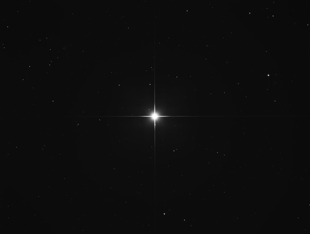
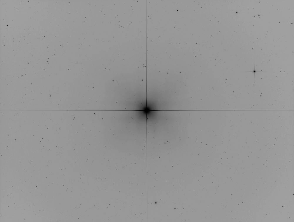
A negative image shows nice small stars and the diffraction spikes are not split:
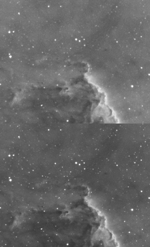
This is 12x10 minutes of ngc7000 in Ha.
Wispy stuff has good contrast.

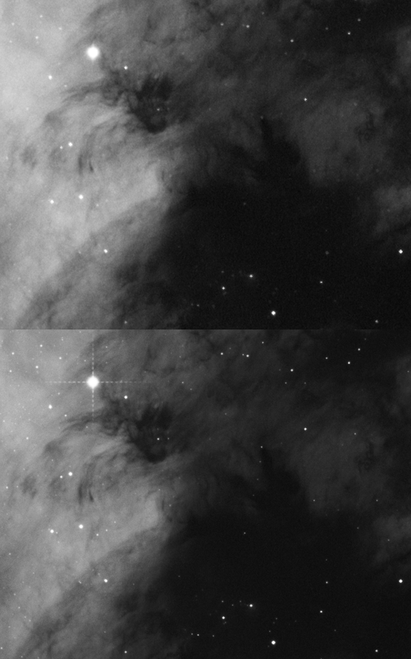
These animated gifs show direct comparison with the same region taken with the Williams Optics 132 refractor in July 2012.
There was only a thin Moon in 2012. Same camera and filter each time.
The Zambuto mirror scope produces much tighter and sharper stars.
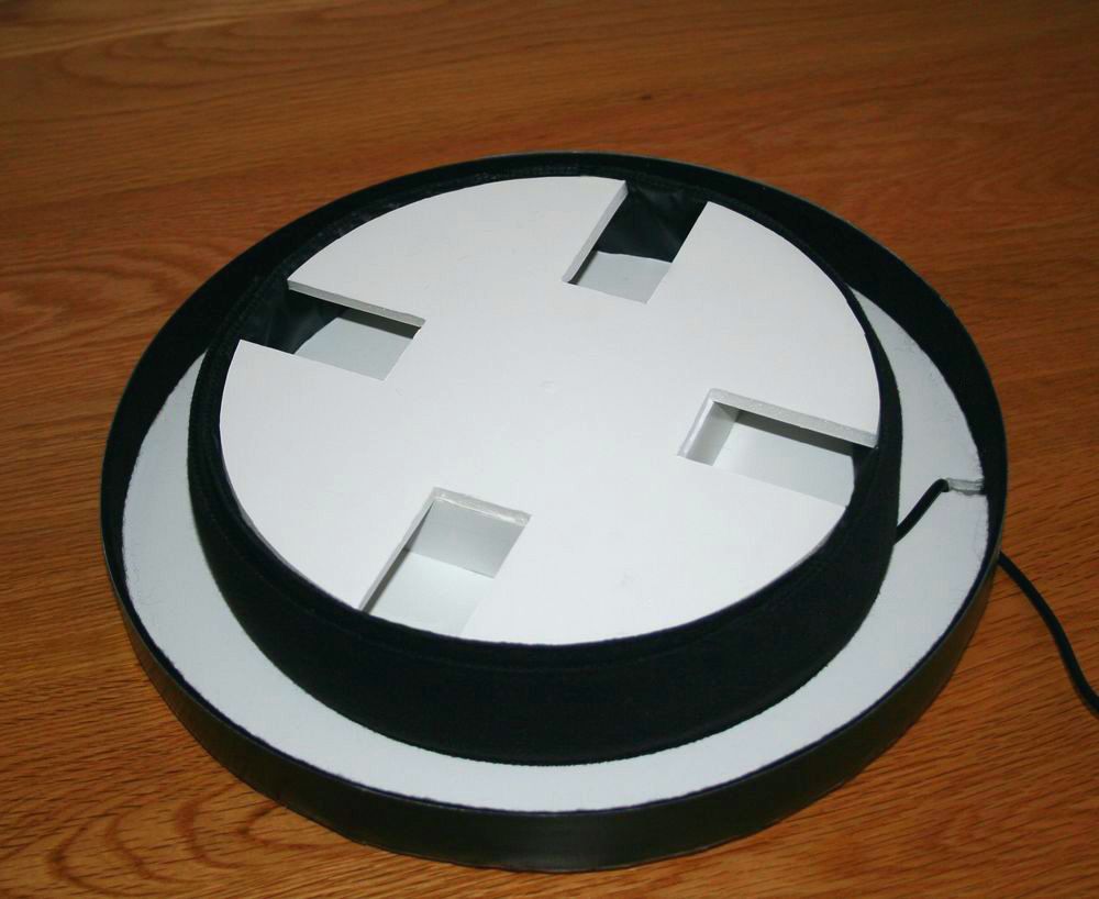
Despite a de-humidifier running in the observatory, it is still possible to get condensation forming
on the telescope mirrors during the damp Winter months.
This eventually damages the coatings.
This dew heater will sit an inch or two behind the main mirror. It will come on for 15 minutes
every few hours, which should keep the inside of the telescope warmer than the outside.
September 18th
The ASA DDM60 mount has to be very accurately balanced. Moving the scope in the tube rings by as little as 1 mm can be too much.
I have made a magnetic puck which attaches to a steel plate and can be easily positioned to give fine balance control.
The puck was made by pouring molten lead into a small tin lid.
8 Neodymium magnets were glued into holes in the lead, and a circle of flocking material stuck over the magnets.
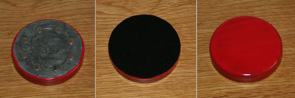
Steel plate grade 430 is magnetic. The puck is held very firmly and will not shift by itself.
