| ASA DDM60 mount - page 2 |
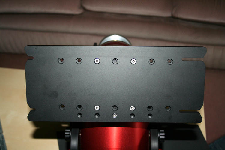
The saddle plate I will need to get my custom made tube rings adapted to fit this plate. I am not yet sure of the final design. |
 |
|
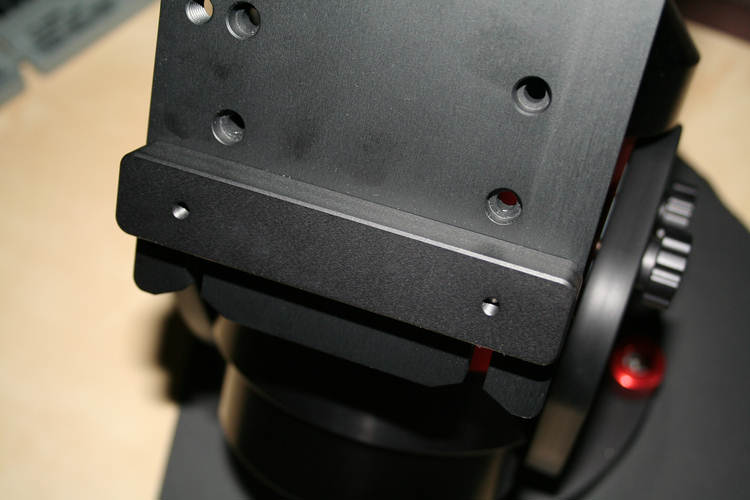
| There are two of
these blocks supplied which attach to the plate. If each block is attached to a tube ring then it enables a 'quick release' system to be used. The tube rings and blocks are fitted to the scope the correct distance apart; the saddle plate is oriented to have the longer slots downwards; the scope is held approximately in the right position and the lower block bolts are slid into the longer slots; the scope is lifted as high as possible and the top block bolts are slipped into the short slots; tighten all bolts and job is done. (Thanks to Robert Pudlo on the Yahoo group for explaining that to me!) |
 |
|
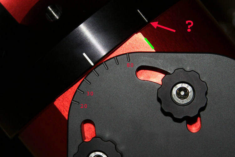
Rough polar angle setting. The markings appear to start at 20 degrees. The white indicator line moves with the RA axis so it seems that you have to align the RA axis North-South by eye and then set the angle. At first I thought that the line marked '?' was supposed to be set next to the point marked with a green line, but then the lines on the other side of the mount are way off. The function of the '?' line is thus unknown. |
 |
|
| Power
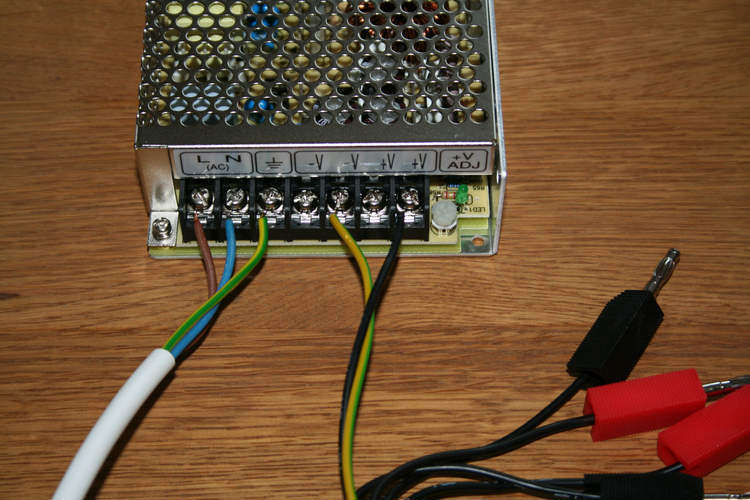
Supply The power supply is a 12.5 amp, 12 volt supply (not supplied by ASA). The main power to the mount is green/yellow to -ve and lead nr5 to +ve. |
 |
|
| Polar
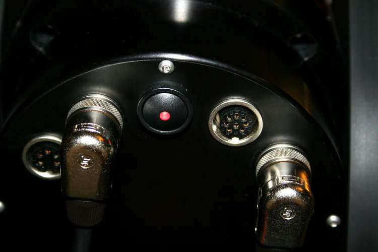
Laser When the power was switched on I was concerned that the laser did not work. Hermann Bimeshofer on the Yahoo group explained that power leads Nr1 and Nr2 also have to be connected. I wired them in parallel to the main supply and not only does the green laser now work but a satisfying red light comes on to show that power is applied! |
 |
|
Installing Autoslew Autoslew has to be downloaded from the ASA site. The ASCOM platform needs to be installed first (http://www.ascom-standards.org/), and if you are going to interface to 'The Sky' you will need the file Teleapi.dll (http://www.ascom-standards.org/Downloads/Plugins.htm). You may also need the .Net framework from Microsoft Version 2 or later. Next task is to install the USB to Serial driver which is supplied on CD. Instructions are as for the DDM85 instructions. The English manual for the DDM60 is not ready yet, so Google Translate has to suffice. When installing Autoslew it is useful to know that Weiter = Next; Abbrechen = Quit; Zuruch = Back; schließen = Close; Alle Benutzer = All Users Needless to say, I missed the line that says 'Please set the right comports before you first start Autoslew because we have to fix a problem here if Autoslew is started with wrong comports.' An email to Philipp Keller who wrote Autoslew brought rapid reassurance that no damage would result. My laptop used ports 4 and 5 and these were duly set in the file E-Servos.ini Autoslew ran without a problem and the mount made a horrible buzzing sound. This is due to the parameters for the motors (P, I and D) being wrong, but after carefully following the instructions to tune the parameters the mount setted down. See here for a simple explanation of PID Control. Perhaps an hour of experimentation passed before the mount could slew without vibration in RA and DEC, up to an impressive 15 degrees per second. This is a bit fast so I settled for 5 degrees/sec as a gentler option. |
||
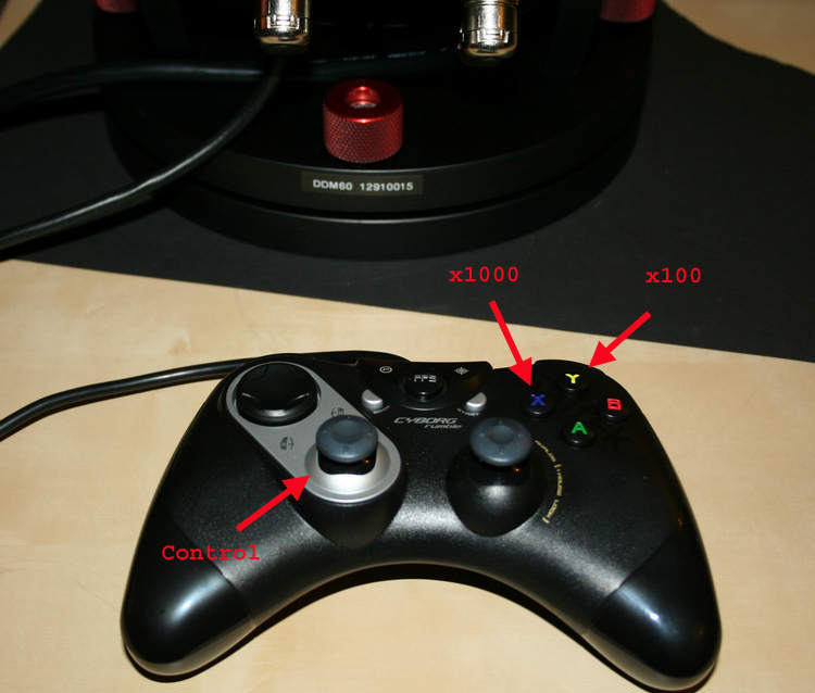
| A standard games
'rumblepad' can be used to steer the mount. The lefthand joystick controls the
direction of motion and various buttons can be configured to give two fast
slewing speeds. I use 'Y' to give 100x sidereal and 'X' for 1000x
sidereal. |
 |
|
| The pier is a
salvage item. It used to be part of an electron microscope. There are three conveniently placed curved slots that will accept six bolts in the adapter plate. Each bolt has a nylon sleeve to make rotation smoother and to protect the bolt threads. |
||
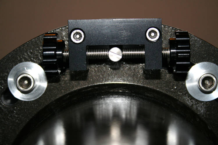
| Rob Januszewski of
Epsilon Telescopes made the
adapter plate. A pin in the plate is positioned between the two knobs. This will give several degrees of azimuth adjustment. |
||
| The azimuth
adjuster seen from
below. |
 |
|
| Top view of the
plate. The inner six holes are for fastening the DDM60
baseplate. |
||
| The DDM60
baseplate in position. The bearing in the centre is what the mount rests on. It can tilt in any direction, so that adjusting the four levelling knobs will give fine adjustment in altitude and azimuth. |
||
|
Next page
|
||