| The Carey Mask |
26th March 2009
The Bahtinov Mask requires you to judge when the central spike is midway between the two angle spikes.
This is quite easy to do, but there is still a little uncertainty in determining the exact centre alignment, especially when viewing in a DSLR viewfinder.
After some experimentation, I have come up with this mask, which is perhaps different enough from the Bahtinov mask to warrant a new name.
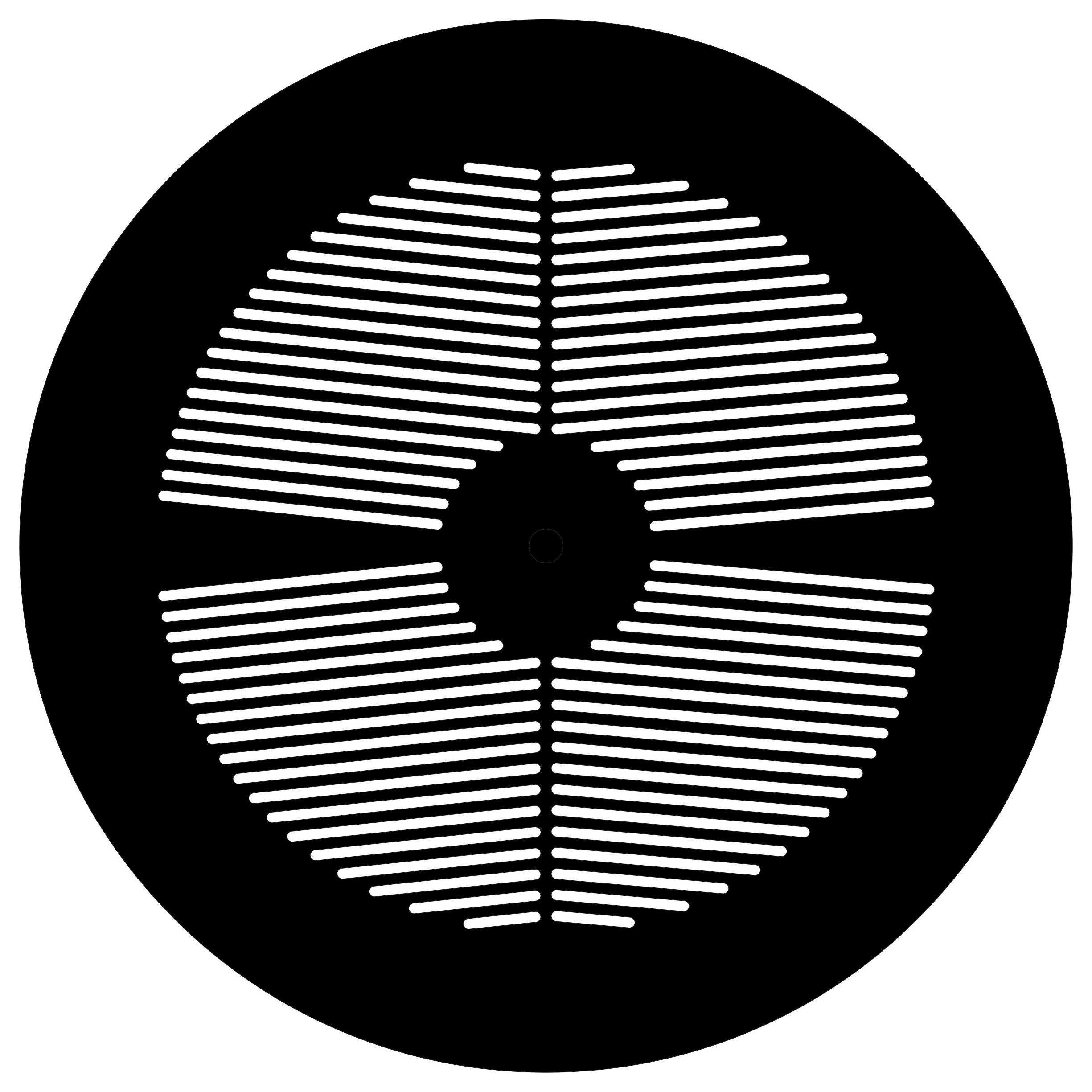
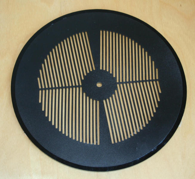
The central spike idea has been abandoned. The angle between spikes has been considerably reduced. Instead of two sloping sets of slits and one central set, there are four sets of slits, with a small angle difference on each side of the mask. In the prototype I used 10 degrees and 12 degrees.
| 12 degrees> | 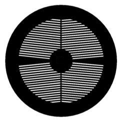 |
< 10 degrees | ||
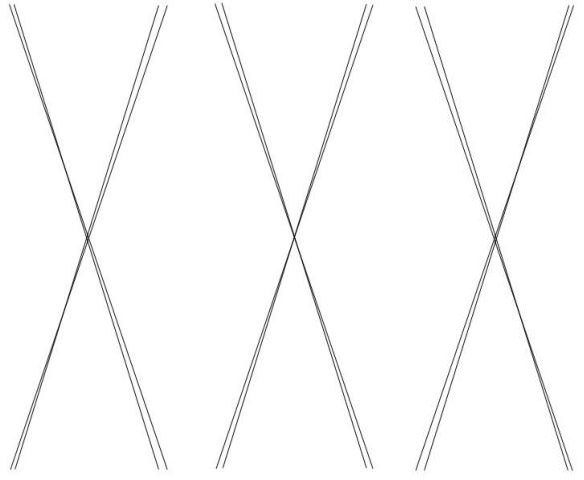
The diffraction pattern produced is two overlapping 'X' shapes, with slightly differing angles.
At perfect focus the Xs will be symmetrical.
Inside and outside focus the Xs will be displaced. Because the angle of each X is slightly different, it will be easy to spot when out of focus, and also which way focus should be altered.
| Inside focus | In focus | Outside focus | |||||||
 |
|||||||||
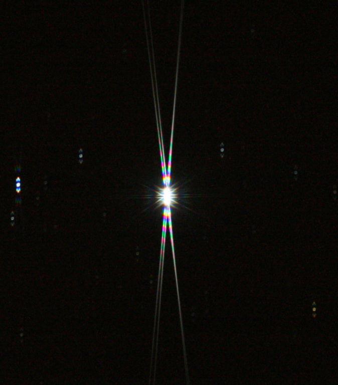
In this example the offset of the Xs causes a noticeable gap between the left hand spikes, but the right hand spikes overlap, appearing to be single spikes. The mask should always be placed on the telescope in the same orientation so that the user becomes familiar with which way to alter focus. In this example on my telescope, because the left hand spikes are 'split' I know that the focus knob must be rotated anti-clockwise. |
 |
||
| Closer to focus,
but the left hand spikes are still more split than the right. Rotate focus knob anti-clockwise a little more. |
 |
||
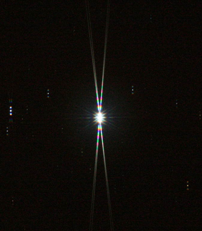
| The 'split' in
the left hand spikes is now the same as the right hand side. Sharp focus has been reached. |
 |
||
| The top part of
the image in detail. It only takes a very small shift in focus to make a drastic change in the appearance of the spikes. |
 |
||
| This example from
a different trial shows that a very small anti-clockwise turn is needed. |
 |
||
This animation shows focus being reached. |
 |
||
| NB | For best results the Carey Mask should be cut
from the thinnest sheet possible. 3mm perspex produced indistinct spikes. 1.5mm card was much better. |
Update: 3mm perspex seems to be suitable for larger aperture telescopes. I have recently made a Carey Mask for my 10" reflector and initial trials show no problems. See here for results. | |
| Below are high resolution jpeg images if you
want to try hand cutting a mask. Right click on the image and follow: Save Picture as... |
The masks have slots with rounded ends which reduces unwanted additional diffraction. | 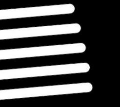 |
 |
Download
a DXF file of a Carey mask for a reflector here
. If you have access to a laser cutter you will be able to try it out. (The DXF file lacks an overall scaling factor, so you will need to resize it to suit your scope). |
||
| This mask is for refractors as it has no central obstruction. | 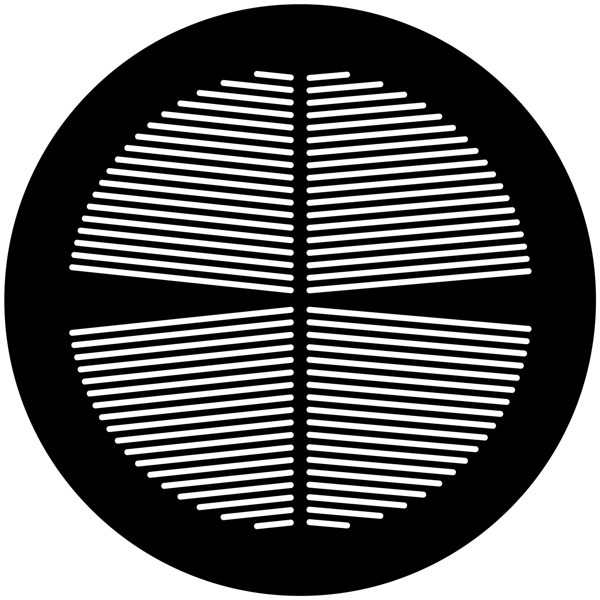 |
Download a DXF file of a Carey mask for a refractor here . |
| Simulation of Carey Mask |  |
||
| Niels Noordhoek, who created the 'Bahtinov Grabber'
, has created superb
simulation software. Any variety of mask can be quickly investigated. It is called 'Maskulator', and was used to create this video showing a Carey mask diffraction pattern as it goes in and out of focus. Click here to download Maskulator. |
What is the best material from which to make the mask?
3mm black perpex did not work well for the Carey mask because diffraction spikes were very indistinct.
(This comment applies to smaller aperture scopes. See here for results of experiments with a 10" reflector)
My prototype cut from photographic mounting card was much better.I then assumed that the thinner the better, and tried a variety of different materials. It does not seems possible to get black Perspex thinner than 3mm. I tried HIPS (high impact polystyrene) and ABS (acrylonitrile butadiene styrene) and both were subject to warping and melting problems caused by the laser cutting.
I had steel and aluminium ones cut but in both cases the heat caused severe warping.
I recently tried 0.5mm clear perspex and the initial results looked promising. I had to spray paint the mask with matt black paint, and because the perspex was very thin I made a 3mm perspex support.
This version also had rounded ends to the slits and I anticipated very sharp diffraction spikes.
However, the star tests were disappointing. The mask is perfectly usable, but the diffraction spikes are not as bright nor as sharp as those with the 1.5mm card!
The cuts appear to be quite straight and clean, and the mask with its 3mm thick support is actually flatter than the card.
A possible cause is that perhaps the spray paint adhering between the slits causes a rounding effect.
Certainly the edges of the paper card are very sharp.
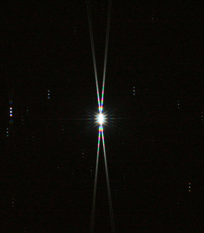
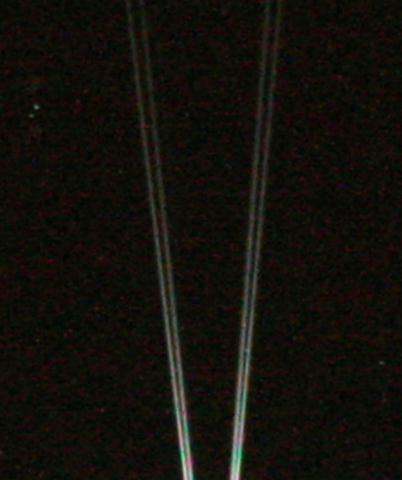
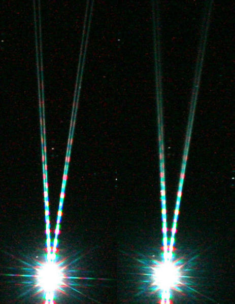
| The
left image is with 1.5mm
card and the right is with 0.5mm perspex. The card produces much longer and brighter spikes which are easier to see in the camera LCD screen. Both were 30 second exposures on the star Vega |
 |
|
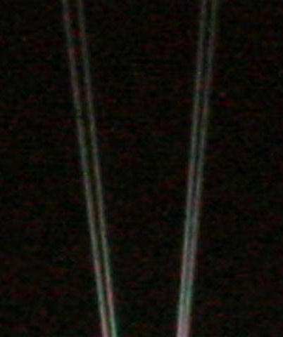
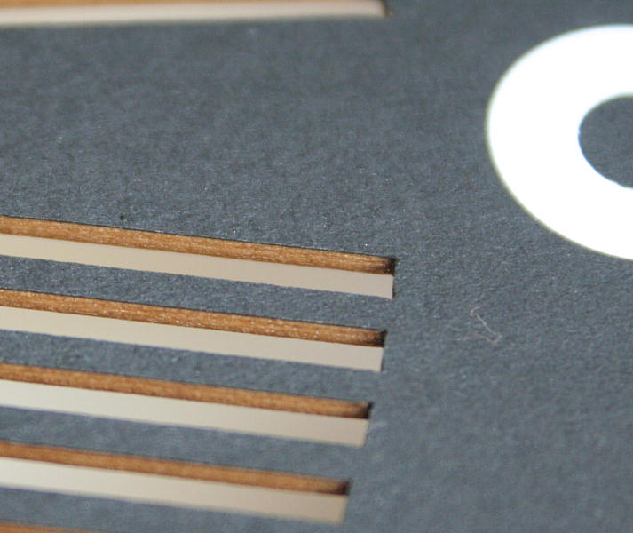
| This
close up shows how sharp the edges of the laser cut are with card. |
 |
Conclusion: I will stick with card for the time being, and carry out a few experiments on different thicknesses. I have seen a source for 1mm thick black mounting card and will give that a try.
Watch this space! Update - black acrylic ended up being the material of choice. I even tried laser cut steel and aluminium but the temperature of the laser warped the mask badly.
How accurately should the mask be centred?
It is quite likely that the mask will be placed on the front of the telescope and the centre will be a few millimeters from the true optical centre.
What effect will this produce in the final image?
I used the maskulator software to simulate this.
Photoshop was used to offset the mask by an amount which is greater than that likely to be encountered in reality.
The animated images below show the two positions of the mask, and the resulting diffraction patterns.
 |
||
| Result:
The positions of the diffraction spikes are unaltered. All that is seen
is a slight dimming, and a change in the pattern close to the centre. Conclusion: The masks do not have to be centred very accurately. |
 |
| The Original Bahtinov Mask |